Facebook
 Google
 GitHub
 Linkedin
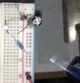
I found this circuit online and I wanted to reproduce it but it fails.
I've got a 9v battery
2n222 transistor
1k resistor
100uF cap
On a breadboard. Nothing happens when I connect the battery. The led doesn't light up. Any suggestions?
I've got a 9v battery
2n222 transistor
1k resistor
100uF cap
On a breadboard. Nothing happens when I connect the battery. The led doesn't light up. Any suggestions?
Attachments
-
 570.4 KB Views: 68