LED driver of keyboard unit broken

Thread Starter

TMJJ

Joined Jan 22, 2019
8
Dear All,

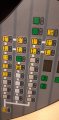
I have a big pcb which is used as keyboard in a mobile application.
The keys have a background light. The backlight excists of 65 leds in serie.

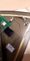
Now at the moment the backlight doesn't work anymore, so I opend the keyboard and started to measure on the PCB. I found out that the there is somekind of LED driver on the back.

https://ibb.co/yRwGH9x
https://ibb.co/yFz3FMx
https://ibb.co/bvKs0pP

On the PCB it looks like the following:

https://ibb.co/zV23m84

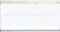
The intensity of the backlight can be changed. When I change it, the input voltage changes from 0 to 8 or to 11.

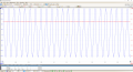
There is no output of the driver. When I measure on a working one I measure some output voltage.
No I would like to change the backlight driver. But I can't seem to find the part to order a new one.

The only number written on the led driver is 1441.

Can anybody help me with finding the part? Or if it even is a led driver?

Thanks in advance,
TMJJ
 

Thread Starter

TMJJ

Joined Jan 22, 2019
8
Do you know what (voltage and current) is required to light the string of LEDs?

Hi Wayne,

I don't know the amout of current which is needed. What I know is the following:

Level Voltage in Voltage out
1 6V 0.5V
2 8.53V 0.78V
3 11.38V 1.12V

I hope this helps already

Thanks,
TMMJ
 

ArakelTheDragon

Joined Nov 18, 2016
1,366
You have to see, is it possible to fix the driver, I can't see the pictures from here(I am

The current must be less than 1 mA, its best to start with 0.1mA and increase by 0.1mA until the LEDs light. It will be hard with such low current.
 

Thread Starter

TMJJ

Joined Jan 22, 2019
8
You have to see, is it possible to fix the driver, I can't see the pictures from here(I am

The current must be less than 1 mA, its best to start with 0.1mA and increase by 0.1mA until the LEDs light. It will be hard with such low current.
Can you see it like this?
The problem is that I can't find the same component package as in the pictures.
 

Attachments

ArakelTheDragon

Joined Nov 18, 2016
1,366
What I meant is from this computer(firewall).

How did you figure out this is a LED driver?

0.Some LED driver specs.
1. Some LED driver PCB.
2. Some LED driver PCB.

A smart approach is to apply voltage to the PCB(if you are sure the inputs are for what you say) and gradually increase the voltage until you reach the needed level, at the same time the current must be kept small (1mA per LED max, not per LED strip) and test will it work. If it does a new driver may be used or another mechanism, however do this at your own risk if you want.

Is the PCB custom made or does it have a model number and part number?
 
Last edited:

Thread Starter

TMJJ

Joined Jan 22, 2019
8
What I meant is from this computer(firewall).

How did you figure out this is a LED driver?

0.Some LED driver specs.
1. Some LED driver PCB.
2. Some LED driver PCB.

A smart approach is to apply voltage to the PCB(if you are sure the inputs are for what you say) and gradually increase the voltage until you reach the needed level, at the same time the current must be kept small (1mA per LED max, not per LED strip) and test will it work. If it does a new driver may be used or another mechanism, however do this at your own risk if you want.

Is the PCB custom made or does it have a model number and part number?
Hi,

It's not a cuystom PCB. It is from a Liebherr Tastatureinheit nr 10102175.
If you search it on google you can find the keyboard straight away.
 

ArakelTheDragon

Joined Nov 18, 2016
1,366
If only your driver is broken (the 3 pin black box), you can use an external voltage and current regulator. Set the current to 1mA and increase the voltage to the expected, then slowly rise the current from 1mA to the exptected.
 

Thread Starter

TMJJ

Joined Jan 22, 2019
8
If only your driver is broken (the 3 pin black box), you can use an external voltage and current regulator. Set the current to 1mA and increase the voltage to the expected, then slowly rise the current from 1mA to the exptected.
Hi,

Sorry for the late reply, but I didn't had time to do the measurements.
Now I took a working pcb from another machine and connected it on my desk. Now I'm able to measure in a better way.
So first of all I connected only the necessary power. (LEDs are not burning at this point)
When I connect 24 volt to the pcb and I measure on the output of the led driver, I had some weird results.
So I connected my oscilloscope to the output of the LED driver and saw that it was an AC output of +/-120V RMS.
The DC component of the output is 1.82V. (See attachements blue trace on attachement).
At this point I measure a DC current of 0 mA and a AC current of 16.45 mA. The input on the led driver at this moment was 20.7V (see red trace on the attachement). So this is not what I expected.

When I push on the button to switches the vehicules lights on, the backlight of the pcb starts to burn.
When I do the same measurements I get the following results.

Then input voltage of the led driver changes from 20.7 to the supply voltage of 24V. This results in a shift of the zero point of the sinus.
The sinus gets shifted higher. This results in a higher DC component. +/- 3.8V DC and an AC of 135V RMS. The current to the LEDs is 18.64 mA.


Anybody an idea what this is? I thought the output would be a normal DC voltage or maybe PWM. But for sure not AC.

Thanks in advance,
Kind regards,
TMJJ
 

Attachments

wayneh

Joined Sep 9, 2010
18,104
That's some wacky stuff. One thing I'd try is measuring voltages with some small load attached because a voltage with no load can be a bit of a ghost. Obviously the lit LEDs are a load and that's fine but I'm talking about the situations when there is no obvious load. Use a 10K resistor for high voltages or a 1K for lower (12V and below) between your meter leads. These tiny loads ensure that the voltage you measure is not just stray noise.
 

Thread Starter

TMJJ

Joined Jan 22, 2019
8
That's some wacky stuff. One thing I'd try is measuring voltages with some small load attached because a voltage with no load can be a bit of a ghost. Obviously the lit LEDs are a load and that's fine but I'm talking about the situations when there is no obvious load. Use a 10K resistor for high voltages or a 1K for lower (12V and below) between your meter leads. These tiny loads ensure that the voltage you measure is not just stray noise.
Hi,

Thanks for the reply! So I just did it.
No change, I still get the sinus wave. Very very strange. I also touched it accidently with my hand.
It was definitly not 2V ;).

The problem is also that I can't see the LEDs. See attachement.
It are the LEDs which light the background of the pushbuttons it self.
It is necessary because a lot of operators need to work during the night.

Kind regards,
TMJJ
 

Attachments

Thread Starter

TMJJ

Joined Jan 22, 2019
8
Something is wrong here. Can you try putting the black box and LEDs on another setup(device, test environment and etc.) then test?
Yes, I can desolder the black box. The LED's are inside the pcb. So I can't get them out.
But I can put use a potentiometer to change the load.

I will try to desolder asap.

Thanks,
Kind regards,
TMJJ
 
Top