So you're repeating the same basic sequence over and over, which seems OK to me.
I have a black thumb, plants die under my care. But I am curious how this works out.
Unless the difference is dramatic I wouldn't worry about too much variation in the current, ±10% is good enough. If it is outside of that look at the real total Vf and recalculate from there.
Your design has another characteristic I like, the resistors are dropping very little voltage, this means really high efficiency and very little heat.
I will keep in mind the ±10% when I start testing.
When I was looking at possibilities for each string given the fixed layout I tried to find the one where the least Watts were used to keep it cool and cheap
Just noticed the vender is stating they use 45° and 33° LED's now ... time to see if I can even find LED's with the selected spectrum in these specs >.<
But thankfully a redesign will be easy now that I have had practice.
I ordered all my parts today, 1540 LED's and a whole bunch of goodies to wire it together. Now to wait for the parts to come and in and go clean off a working space so I can hammer these guys out.
I am working on the physical layout right now so it fits on a PCB and is tight, I have some preliminary stuff setup and now I am just working out where I would like the lights to go, since mixing them is key.
Be sure to have your body and bench static protected.
LED's aren't usually to picky about handling but with that many, you could build up a big charge just moving your arms around. Then you pick up an LED, or an assembled board of them, and ZAP!
Never though of static being responsible for a LED's death before >.< and I use to assemble laboratory equipment and we had like 1000 LEDs in a plastic bin on metal shelves!
The tables had wood tops with carpet (really thin carpet) over them as our work area but their support was made from the same steal as the shelves.
I will probably be working on a stone surface but I will make sure to take precautions just in case When I am indoors I am often barefoot anyway so I should be well grounded on a stone or concrete surface.
Ok some updates ...
I have 12 units assembled and more to come but I just remembered to test the current ... >.<
So I grabbed several boards and tested the voltage across different strings. (rounded up to nearest 100th)
String 1 4.3V / 220Ω = 19.55mA
String 2 4.4V / 220Ω = 20mA
String 3 2.5V / 150Ω = 16.67mA
String 4 4.6V / 220Ω = 20.91mA
Do I take the highest Current and see what the % of deviation for the strings of each string to make sure its ±10%?
Example:
String 1 ( ( 20.91mA - 19.55mA ) / 20.91mA ) * 100 = 6.5%
String 2 4.35%
String 3 20.28% <<< this is why I ask btw
String 4 0%
I would hate to keep wiring these if they are wrong and rather go back and fix the 12 I have already assembled.
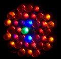
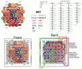
Below are some pictures for reference and progress The white dots in are anode leads.
I did, here is the quote from the post ... 2.5V was the measurement across the resistor in string 3
My meter isn't sensitive enough to read the resistance of the resistor that well to tell if its a 175Ω vs 150Ω ... but they are ±5% so they could be 142Ω to 157Ω
Should I set up a test on my bread board and test to see what the average vF is for a couple of the same LED?
Vfs are notoriously fickle, which is why I recommended measuring them. The 16ma could be bumped up with a 130Ω resistor (or a 750Ω resistor in parallel).
As long as nothing is too high I don't think I would worry about it. LEDs are not that linear, at 16 ma you are still getting most of the light you would at 20ma, and it will last a long while.
So given the voltage drop is 2.5V across the resistor if I divide by 20mA (E/I = R) I get 125 Ohms, but the closest common resistor is 130Ω
With 130Ω used the current through string 3 would be 19.23mA
So it would use 41.67mW over the resistor and 411.13 mW over the rest of the string (P=IE)
PIR EIR WAV ... P=I^2 x R E = I x R W = A x V
(per air wave)
will commit this phrase to memory
I think I will get the 130's anyway just to confirm the change so I can put it in my assembly guide. I looked at the output curves for 16mA vs 20mA and they LED's would only be 75% their brightness compared if kept at 16mA.
Thanks for the advice, will post updates soon. If it is desired I am making a construction tutorial for the aquaponics community I am part of and will be happy to post it here if desired ...
So just crunched numbers to make sure each unit was under the 2 watt limit and before and after a change from 150Ω to 130Ω I should be fine ... the question now is should I change string 4 to use 240Ω instead of 220Ω bringing the current down to 19.16mA ? this would give me 3 extra watts overall versus the .5watts I will have left on the power supply by switching string 3 to 130Ω ... 1863mW(with 130Ω and 240Ω changes) vs 1980mW (with 130Ω change only)
Thoughts?
I assume it wouldn't matter too much to have a little of give in the power supplies given they are well regulated and the units will not heat up enough to change resistance that much correct?
long time since I last posted as I had to put the whole project on hold. Today I brought out all the parts and lights I was working on and started to update my memory with what I was doing.
I remember having an issue with current imbalance so I took some new measurements across all the resistors in each string to find the current through them.
These were relatively cold measurements but I noticed the voltage increasing in following measurements so I waited for it to level out and got the following.
This surprised me but then I remembered electronics change their attributes when temperature changes. So my main concern now is string 4 taking too much current. I do have some 240Ω resistors sitting around I could swap the 220Ω for and this should bring it down to about 23mA I think.
The good news is I already started to order the other parts I need for my plants so I will have them soon but now that is putting pressure on me to finish this project
Yes, the forward voltage of LEDs drops as they heat up so the current increases. It might be worth increasing all the resistors slightly, because in summer the LEDs will be warmer.

 Facebook
 Google
 GitHub
 Linkedin