The SMD LEDs of Cree need to be soldered to MCPCB. But since even MCPCBs are a bit poor in heat sinking, we'd need to attach another heat sink. That's what I got from searching the internet anyway
So, would CPU heat sinks work? I'm thinking they ought to be some of the best, and combined with a cooling fan, should manage the temperature pretty well...
CPU heatsinks could work, but I don´t see enough info to judge this. IIRC you said you want to power it up in short bursts, so they will probably be enough. But still, you should get some info on the LEDs, the MCPCB and the heatsinks and do the thermal calculations first.
I would have done the thermal calculations if I had any idea what the thermal resistance of the CPU heat sink would be... And since its forced convection, wouldn't I need to consider air speed and all that detail?
If you take the typical pentium 4 and further heatsink like this , I would guesstimate that the ambient inside PC is 35°C, peak temperature of a CPU die is usually around 65°C, and the CPU typically has TDP of 65W (desing power for maximum load), so that gives ~ 0.5K/W with the fan fully on, so a 1K/W to be on the safe side.
Or you can bolt a transistor to it, put similar power into it and measure the temperature rise.
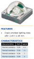
Cree XLamp XP-C ideal Junction temperature Tj=25°C
Maximum Tj = 150 °C
Junction to solder point thermal resistance
of red, Rjsr= 10°C/W
of Green, Rjsg=20°C/W
of Blue, Rjsb=12°C/W
Thermal grease datasheet does not seem to give thermal resistance, just says 'conductive'. So I'm assuming it to be zero.
Thermal resistance of MCPCB is near 5°C/W(Tmc)
Thermal resistance of heat sink: 1°C/W
Cree LED ratings: 4 X (0.77 W + 1.19 W + 1.115 W) by considering forward drops and maximum current.
4 heat sinks, so consider 3 LED per heat sink (12 in total)
Pdr=0.77 W
Pdg=1.19W
Pdb=1.115W
Where Pd is the total power dissipation.
Assuming ambient 30°C,
Tj=Ambient+ Rjs of each LED*its Power dissipated+ MCPCB temp. drop+heat sink drop
Tj=Ta+ Pdr*Rjsr+Pdg*Rjsg+Pdb*Rjsb+5°C (per LED, MCPCBs are individual)+(0.77W+1.19W+1.115W)*1°C/W
Tj=30°C + 74.88°C+5°C++(0.77W+1.19W+1.115W)*1°C/W
Tj=112°C
I guess I should be safe... Maximum is 150 °C
Or am I wrong?
The surface-mount LED is soldered or glued to the aluminum STAR thermal substrate.
The thermal substrate is mounted on a heatsink or on a Metal Core Printed Circuit Board (MCPCB). The surface mount LED can also be soldered directly to a MCPCB by a soldering machine or an oven.
12 LEDs will produce about 30W of heat. I don't know if 4 small CPU heatsinks with fan can cool well enough.
Sort of.
The Cree tiny surface-mounted LEDs are reflow soldered onto a Metal Core Printed Circuit Board (MCPCB) or fastened to a Star metal substrate or to a heatsink with an adhesive.
I'd like to tell you all that the block level testing of our circuit was complete and successful!
It would never have been possible without all of your help!
On another note, how can I attach an MCPCB to the CPU heat sink without using screws? I want the MCPCBs to stick to the heat sink. I believe thermal grease is only an interface material, and thus cannot be used for the sticking purpose?
Can I use superglue? Will it melt away at high temperatures of MCPCB? Does it have a high thermal resistance? Could someone help me with an alternative?
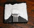
I don´t think glue will work because you need to have some pressure on the paste for it to work properly. Maybe you could use some PCB or other material to make a plane the is screwed on the sides to the normal heatsink mounts, and has a hole in the middle that holds the LED module?
Yeah it´s mostly up to your ingenuity to make something that will hold the LEDs down. Could be a piece of plastic, a guitar string screwed to the heatsink.. basically anything that will allow you to exert some pressure on the pcb and withstand say 100°C.
That's definitely new info, thank you! Am I correct in assuming thermal grease alone wouldn't help in sticking? Also, if I cannot get a particular brand, what do I call silicone putty? What should I ask for, I mean?
 Facebook
 Google
 GitHub
 Linkedin