Hi,
The forward voltage is assumed to be between 3.6 to 4 volts. This is normal for most, I understand. We're at a debate on what LEDs to actually use. Importing Luxeon star LEDs would be a bit impractical. Sure, element14 supplies this, but in our currency, Luxeon costs a bit too much for a student. We're thinking Cree or Avago for substitute. Anyway, the maximum forward voltge should be 4 or 4.2 V, and I'm leaving some voltage extra for margin in the secondary, just in case. We need intensity control, so Vf may vary a little. We'll need two more days to sort it out, but for now, I'm assuming Vf=4.
I don't know about transformer ratings I know I need a step down transformer, and I think it needs about 5 A current capability in the secondary (I think?).
The heat sink is meant for TO-220, according to the website element14.
So wouldn't LM317T fit? The heat sink showed up as an accessory to the said IC.
In that matter, what other elements would need heat sinks?
Thank you . I have to go to sleep now...Its 12:40 AM here and I have class tomorrow lol.
If your transformer is 24VAC then its peak voltage is 34V and its output is +32V minus a few volts of ripple. Maybe +29VDC.
You ASSUME the LED voltage to be 4V but each brand and color is different. The minimum voltage might be 3.5V and four in series use 14V.
The LM317 drops 1.25V across its current-sensing resistor so it has across it 29V - 14V - 1.25V= 13.75V. Therefore its maximum heat dissipation is 13.75V x 350mA= 4.8W.
The tiny heatsinks you selected allow the case of the LM317 to heat 55 degrees C for each Watt so the case will be 55 degrees x 4.8W= 264 degrees C and the chip of the LM317 will be much higher than that. The temperature of the ambient air adds to the heating. The maximum allowed chip temperature is only 125 degrees C.
Therefore the heatsinks are much too small for your very high rectified and filtered voltage.
The LEDs also need heatsinks since each LED dissipates a maximum of 4.5V x 350mA= 1.58W. A 3.5V LED dissipates 1.2W of heat. If the heatsinks are in an enclosure then the heating is concentrated and the enclosure becomes an oven.
EDIT: I calculated with the tiny surface-mount heatsinks on the first page of the datasheet. The heatsinks for TO-220 are much bigger and cool better. But maybe not enough.
Yes those are for TO-220, but the question is if the are large enough to keep the lm317 cool. So to get the worst case, lets assume the LEDs will have Vf a little lower than you thought, so you will end up with 6V from in to out of the lm317, multiply this with 350mA and you get 2.1W dissipation.
Thermal resistance from junction to the cooling tab is 5 K/W, so you will have 10K more inside the chip than outside. Maximal junction temperature is 150°C, so lets stay conservative and aim for 100°C max on the cooling tab. Now lets assume the ambient temperature is 50°C, so you need to dissipate 2.1W over 50K, so the heatsink must have 23K/W or better thermal resistance, and that minus 1 or 2 K/W for the tab-to-heatsink junction. With forced cooling you could use smaller heatsinks.
I just noticed the PDF with the heatsinks hase more than one page Which exact type did zou want to use?
If your transformer is 24VAC then its peak voltage is 34V and its output is +32V minus a few volts of ripple. Maybe +29VDC.
You ASSUME the LED voltage to be 4V but each brand and color is different. The minimum voltage might be 3.5V and four in series use 14V.
The LM317 drops 1.25V across its current-sensing resistor so it has across it 29V - 14V - 1.25V= 13.75V. Therefore its maximum heat dissipation is 13.75V x 350mA= 4.8W.
The tiny heatsinks you selected allow the case of the LM317 to heat 55 degrees C for each Watt so the case will be 55 degrees x 4.8W= 264 degrees C and the chip of the LM317 will be much higher than that. The temperature of the ambient air adds to the heating. The maximum allowed chip temperature is only 125 degrees C.
Therefore the heatsinks are much too small for your very high rectified and filtered voltage.
The LEDs also need heatsinks since each LED dissipates a maximum of 4.5V x 350mA= 1.58W. A 3.5V LED dissipates 1.2W of heat. If the heatsinks are in an enclosure then the heating is concentrated and the enclosure becomes an oven.
EDIT: I calculated with the tiny surface-mount heatsinks on the first page of the datasheet. The heatsinks for TO-220 are much bigger and cool better. But maybe not enough.
Sorry for not giving the exact model name. Its 270-AB which hass a thermal resistance Thermal Resistance: 70°C @ 4W . Does this mean it allows the IC to heat upto 70 degree per watt for a 4W load?
Thank you for explaining the secondary voltage. Here, a meter reads the supply voltage to be 240V, so I guess its the RMS value? Thus I'll have 339V as peak. I'll need to change my simulation. I'm thinking of decreasing the turns ratio so that I'd get about 18 V DC at the input side of LM317T.
In the worst case scenario, I'll assume an 8V drop across the LM317T, so its 2.8W, right? So then the cooling would be 70 X 2.8=196°C. Will this heat sink be enough?
Yes those are for TO-220, but the question is if the are large enough to keep the lm317 cool. So to get the worst case, lets assume the LEDs will have Vf a little lower than you thought, so you will end up with 6V from in to out of the lm317, multiply this with 350mA and you get 2.1W dissipation.
Thermal resistance from junction to the cooling tab is 5 K/W, so you will have 10K more inside the chip than outside. Maximal junction temperature is 150°C, so lets stay conservative and aim for 100°C max on the cooling tab. Now lets assume the ambient temperature is 50°C, so you need to dissipate 2.1W over 50K, so the heatsink must have 23K/W or better thermal resistance, and that minus 1 or 2 K/W for the tab-to-heatsink junction. With forced cooling you could use smaller heatsinks.
I just noticed the PDF with the heatsinks hase more than one page Which exact type did zou want to use?
The temperature rise at the surface of the heatsink is 70 degrees C for a dissipation of 4W. So for 1W the temperature rise is 17.5W.
For a dissipation of 4.8W then the temperature rise for the heatsink is 17.5 degrees x 4.8W= 84 degrees C.
The temperature rise from the chip to the case of the regulator is 4 degrees C for each Watt so its total temperature rise is 4 x 4.8W= 19.2 degrees.
The ambient might be 30 degrees C.
Then the chip temperature is 84 + 19.2 + 30= 133.2 degrees C which is TOO HOT!
The max allowed temperature of the operating chip is only 125 degrees C so the little heatsink is too small.
I'll try to get a better heat sink
Will decreasing the transformer secondary voltage solve the problem though? Because either today or tomorrow I'll decide on the LEDs and I'll know the exact drop on the LEDs. So, if I choose the transformer rating so that there's only a 4V drop across the LM317T (240/16 VAC), would problems still exist? The reason I'm a bit reluctant to change the heat sink is because of the cost difference. From what I've found, there's a very significant cost increase for similar ones with better capacity.
Don't they have an inbuilt heat sink? If that's not enough, what kind of heat sink should I use? I've never used heat sinks before, so I have no idea. Would a cooling fan suffice? I don't know if a cooling fan can cool the 20 LEDs. Is there a thermal pad or something? I've heard of something called a thermal grease. Will that also be needed?
Would I need to solder the heat sink to the LED, or does the given model take care of that?
Please help
EDIT:
Found a better heat sink, I think!
MC33277 in http://www.farnell.com/datasheets/357680.pdf
Will that do?
I'm aiming at a 240/16 VAC transformer now, as I hadn't considered that they were RMS values and needed to be multiplied by sqrt(2) to get the DC output. What should be the current rating?
Also, could you help me with the approximate value of the thermal resistance I'd need for an LED heat sink, assuming I need one for the LED attached?
Your link to the Avago LED does not work so we don't know its spec's. Then we don't know if a 16V transformer produces not enough or too much voltage. If you post its part number then we can look up its datasheet.
The transformer must have a VA spec which is the amount of power it must transfer to the entire circuit, not just to the LEDs. The bridge rectifier, the LM317 regulators and the current-sensing resistors also heat with some power from the transformer. It is simple to calculate the current rating needed of the transformer when the needed VA rating is calculated.
Your new heatsink is even smaller that the previous one so it will probably cause the LM317 regulators to overheat.
Without having the spec's for the LEDs then we don't know the size of a heatsink they need.
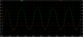
You show an oscilloscope trace of pulsing DC (from the bridge rectifier?) that averages about +9.5V. It is a 50Hz sine-wave instead of the 100Hz triangle-wave expected from a bridge rectifier so there is something wrong with your power supply.
Your link to the Avago LED does not work so we don't know its spec's. Then we don't know if a 16V transformer produces not enough or too much voltage. If you post its part number then we can look up its datasheet.
The transformer must have a VA spec which is the amount of power it must transfer to the entire circuit, not just to the LEDs. The bridge rectifier, the LM317 regulators and the current-sensing resistors also heat with some power from the transformer. It is simple to calculate the current rating needed of the transformer when the needed VA rating is calculated.
Your new heatsink is even smaller that the previous one so it will probably cause the LM317 regulators to overheat.
Without having the spec's for the LEDs then we don't know the size of a heatsink they need.
You show an oscilloscope trace of pulsing DC (from the bridge rectifier?) that averages about +9.5V. It is a 50Hz sine-wave instead of the 100Hz triangle-wave expected from a bridge rectifier so there is something wrong with your power supply.
Sorry about the link. I've noticed a typo in the form of a \ at the end that does not occur in links. sorry~ The part is ASMT-Mx00, just googling it gets the result and the link they provide is the same!
The LEDs would need 4X 350 mA current at max, so I should be safe with a transformer able to provide 3 or 4 A current at secondary, right? so the VA rating would be 16X4=64 VA?
How much thermal resistance would you recommend for the heat sink? I'm a bit lost on that.
The oscilloscope trace is that of the transformer, before the rectifier.
I just attached it because I thought it would be helpful to determine the rating...
With those LEDs, what heat sink should I select? I've seen something about 'rectangular' and 'circular', but I have no idea. What would I do with the heat sink? Put some thermal grease and stick the LED to it? But the datasheet shows an LED with two leads, how would I use a heatsink? Will I need an LED fixture?
Please help!
The tiny LEDs are "surface-mount" style which needs a heatsink. But they are too small to bolt to a heatsink so their metal tab is soldered to a large-area of copper on a pcb.
It will be very difficult to solder, usually a machine solders it.
You should use "normal" STAR LEDs that are bolted to a "normal" heatsink.
You should select STAR LEDs that do not need to be operating at their absolute maximum allowed continuous current. Most STAR LEDs have 700mA as their absolute maximum allowed continuous current.
The red or amber LEDs have a voltage that is much less than the blue or green LEDs so the LM317 driving the red or amber LEDs will get VERY hot unless more red or amber LEDs are connected in series or unless a resistor is used in series to share the heat.
I'm having trouble finding high brightness or high power LEDs with a star type PCB. Luxeon seems to be the only manufacturers, and I've searched element14 India. They're out of stock, and it costs way too much. If I were to contact Luxeon, shipping charges would be high too, so its not really that much affordable. Is there any other cheaper alternative to cooling high power LEDs? We're not aiming at continuous operation. The LEDs have to light up just long enough to measure the short circuit current through a solar cell(done manually for now), as our objective is to measure the spectral response. Would heating be that much of an issue here? Its just a prototype.
So, are there any cheaper alternatives to cooling these high power LEDs?
High power LEDs have a very wide beam angle. Cheap ordinary LEDs are also very bright because their plastic case focusses the beam into a very narrow angle and they do not get hot. Maybe you can use them instead.
The thing is, LED Solar simulators use high power LEDs. If I use normal ones, it wouldn't be a real prototype. Also, since their current requirement is low, there won't be a real challenge. We've already submitted the proposal, too...
What I meant was would there be alternatives for the cooling system? An alternate way to cool them? And would cooling be a problem if I'll only need to light the LEDs for a few seconds?
High power LEDs are never used for only a few seconds so they are always used with heatsinking. You will be risking burning them out. The datasheet does not list the duration before destruction, you will need to see that for yourself.
Also, look at the datasheet to see how the light output reduces as they heat up.
The tiny LEDs are "surface-mount" style which needs a heatsink. But they are too small to bolt to a heatsink so their metal tab is soldered to a large-area of copper on a pcb.
It will be very difficult to solder, usually a machine solders it.
You should use "normal" STAR LEDs that are bolted to a "normal" heatsink.
You should select STAR LEDs that do not need to be operating at their absolute maximum allowed continuous current. Most STAR LEDs have 700mA as their absolute maximum allowed continuous current.
The red or amber LEDs have a voltage that is much less than the blue or green LEDs so the LM317 driving the red or amber LEDs will get VERY hot unless more red or amber LEDs are connected in series or unless a resistor is used in series to share the heat.
From searching the internet and watching tutorials, I've found that Cree LEDs are comparatively reliable and cost effective. http://www.cree.com/~/media/Files/C...d Modules/XLamp/Data and Binning/XLampXBD.pdf
I find Luxeon a bit costly. Since all LEDs from Cree seems to be surface mount, I decided to lookup the subject. I've found that this is the way to use them.
-Attach the SMD LED to a thermal substrate(Heat sink pad) using solder paste and heat it using heat gun.
If I do not have a heat gun, can I place the solder iron near the SMD device so that the solder melts off, then place it on the heat sink pad which already had sufficient solder paste?
By heat sink pad or thermal substrate, I mean something like:
Would I need a heat sink after the thermal substrate? I'm only using the LED for a little while (About 10 seconds) in a single stretch, so will that be a problem?
If I need another heat sink, what heat sink should I select? I'd like it to be the lowest price possible (I am a student, and this project is only for demonstration, not actual use) to achieve its purpose. I've heard of MCPCBs and aluminium heat sinks. Which would be less expensive? Can someone link me to an adequate heat sink for this in element14 or mouser?
I need to place these LEDs as close as possible to each other. What would be the minimum spacing? Please consider this when suggesting heat sinks.
I understand there are MCPCB heat sinks, Aluminium heat sinks etc... which one would be of a lower cost? Can I use a single large heat sink for multiple LEDs?
Attach the SMD LED to a thermal substrate(Heat sink pad) using solder paste and heat it using heat gun.
If I do not have a heat gun, can I place the solder iron near the SMD device so that the solder melts off, then place it on the heat sink pad which already had sufficient solder paste?
Your soldering iron might destroy the tiny surface-mount LEDs.
Would I need a heat sink after the thermal substrate? I'm only using the LED for a little while (About 10 seconds) in a single stretch, so will that be a problem?
I do not know how long the LED with a soldered substrate heats then is too hot.
If I need another heat sink, what heat sink should I select? I'd like it to be the lowest price possible (I am a student, and this project is only for demonstration, not actual use) to achieve its purpose. I've heard of MCPCBs and aluminium heat sinks. Which would be less expensive? Can someone link me to an adequate heat sink for this in element14 or mouser?
If heat sinks are close together then a fan is needed.
I understand there are MCPCB heat sinks, Aluminium heat sinks etc... which one would be of a lower cost? Can I use a single large heat sink for multiple LEDs?
I have never seen a metal core pcb and you probably also have not and will never see one. Aluminum heat sinks for power transistors are very cheap in North America.
Will this do? I'm thinking of attaching the LED thermal substrates to this big sized heat sink. I'm guessing I'll only need this? Or are those of Power transistors cheaper?
How would I cool it with a fan? It's large, so how can I use a single fan? I have no idea how to use a fan.
Instead of guessing, you should CALCULATE the thermal resistance needed by the heatsink. That one is pretty big but I don't know how many LEDs you will mount on it.
You also must know the thermal resistance of the adhesive you will use to mount the LEDs.
Wouldn't the spacing also affect these heat sink cooling?
I'm thinking of this alternative:
A CPU heat sink would be about 5 cm X 5 cm area. I'm going to put 4 of them together to form a square and attach the MCPCBs (I found out that the thermal substrate ARE the MCPCBs, and they are available at a reasonable cost...) to the heatsink. Then I'm going to cool them using a CPU cooling fan.
Since CPU heat sinks would be the best out there, wouldn't this work? I happen to have some spare... Then I'd save some and recycle.
 Facebook
 Google
 GitHub
 Linkedin
 I know I need a step down transformer, and I think it needs about 5 A current capability in the secondary (I think?).