I typically use 1N4007 for rectifiers and catch diodes, and 1N4148 for logic functions etc. Just when the demands supersede the 1N4007 I look for something that fits the task better, obviously a switching converter or RF detector needs it´s specific diode.
Hi all,
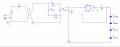
I've simulated the entire system with Pspice, by preparing the schematic with Orcad capture 16.3. Instead of high power LEDs, I'm using 1N5334B zener diodes as dummy load, which has a reverse voltage of
3.6V @350mA.
Figure:
Transformer is a 230/30 V with coefficient of coupling 1.
For better circuit layout, I've made a net alias from the rectifier output terminals, as 1 and 2. The capacitor is for filtering, and then it directly goes to the current regulation circuit. R1=3.57 Ω, so the constant current output should be 350 mA.
I get some weird readings:
Connected as shown in figure: Current through the load: 300 nA (Which should be 350 mA)
Theres a difference of mA and nA. What went wrong?
Voltage drop across D5:12 V (should be 3.6 V)
Connected with the load reversed (direction of zeners reversed):
Current through load:-350 mA(where did the -ve sign come from?)
Voltage drop: 1.6 V->passes through D5->0.8 V->remains the same even after passing through more zeners.
In that schematic there is NO ground at the secondary side of the transformer.
You have one at the secondary side of the transformer AND one side of the bridge rectifier.
Hi everyone!
The LM317 regulator model I used for Pspice had some problems with temlates and some other stuff. After working on it for 6 hours and giving up, I was able to simulate the same circuit easily using LTSpice . I got the desired readings, so I guess I can proceed with implementation?
One final question:
Would I need an EMI filter for the power supply, or will the current regulator take care of all the troubles?
Unless you will be using this in a steel foundry or some other place with huge motors etc., you don´t need an EMI filter. The circuit won´t produce any EMI, and the interference in a typical household socket is usually not that bad to worry about.
The transformer itself can filter out quite a lof of HF noise, and the power supply caps and regulator should take out the rest. I suggest you add a few 100nF ceramic or film capacitors at the main supply and close to where the regulators will be.
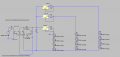
I don't know if I've understood where to place the capacitors, I've placed them anyway. Please verify
The figure has 3 LED strings and therefore 3 current regulators. Anything I should be careful about while handling this circuit?
I guess the small capacitors are used to handle noise and transients?
I've attached figures of the completed project without and with the modifications you suggested. Please verify that I've connected the 100nF capacitances(C2 to C7) right.(I'm not sure)
Thanks
I was doubtful about that. C2, C3 and C4 would suppress noise, right? But won't C2 just get added to the 1mF capacitance? Sorry if it's a stupid question...
It´s not a stupid question. The thing is that large electrolytic caps have paraistic series resistance and inductance, which make them perfrorm pretty bad at high frequencise, so over a certain point they don´t even act like a capacitor anymore. This is true for all capacitors, but ceramic and tantalum caps have this point higher than the electrolytic caps, so you typically use electrolytics for the low frequency ripple and bulk capacitance, and a sprinkle of ceramic or other caps to help with the high frequency stuff. I´ll try to find one video on this.
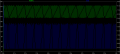
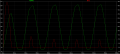
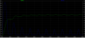
The ripple waveforms are attached. Wouldn't the constant current regulators take care of that? The output I get is still 350 mA...
Also, the current ripple shows near 40A initially, stabilizing to a maximum of 4A. But I understand that 1N5400 can only handle upto 3A? I guess the first 40A would come under surge current, but the rest, showing 4A, wouldn't it be overcurrent for the rectifier diode using 1N5400?
The components selection guide bertus suggested only had a maximum of 3A capability for diodes.
3A continuously, the average value would be much less, so you should be safe with those diodes. Datasheet says Average rectified forward current is 3A at 75°C ambient temperature, so don´t worry about that.
Yes the current regulators will take care of the ripple but there are other things to consider. First, the electrolytic cap datasheet should somewhere state the maximum permissible ripple current, so check if you are below that.
Second, you want to have the secondary voltage as low as possible, so the power lost in the regulators is minimal. With high ripple you need to have the voltage higher so the input voltage on the regulator never drops below the minimum and the regulator doesn´t stop controlling the current.
Frankly, 8V of ripple on a 24V supply is way too much. So if you use say 3x 2200uF caps, then you shold have about 1/6 of the voltage ripple and 1/18 of ripple current on each capacitor, so your caps will have a longer and happier life.
Thank you for explaining that, and Dave's vedio. Both are extremely useful.
Is the Dave in youtube the same guy here in the forums? He's wonderful at explanations. I'll be sure to watch all of his videos.
Hi again....
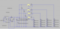
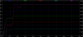
Now there's another issue. I checked the current output of the current regulator through R1, and found that the current is in the opposite direction. Please see the image.
The LEDs get the current in the required direction, but when I check the current through the resistors across 1.25V reference, I get this problem. Is that really a problem or is it a LTSpice quirk?
Hello again,
I've done some more research on the components for the project and come up with the following:
I need white LEDs as well, thus increasing the current rating (4 X 350 mA, with all LEDs having 350 mA)
For the rectifier, I'm using a diode commonly known as 6A2, the 6A, 200 V model: http://www.diodes.com/datasheets/ds28009.pdf
I'm attaching some files with the simulation results. Please check if I've made any horrible mistakes.
I really have no idea how to give specification for a transformer. I want a 240/24 V transformer and it should be able to handle the current shown. Please help me Should I have a power rating or what?
Finally, we have the LEDs and the picture shows voltage drops and current. Thus all constant current supplies can be assumed to draw 350 mA. The picture is based on the highest current case. Please help!
 Facebook
 Google
 GitHub
 Linkedin