Learning LTSpice

Thread Starter

djsfantasi

Joined Apr 11, 2010
9,237
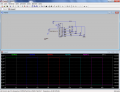
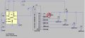
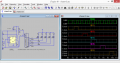
Been trying to simulate a chaser circuit in LTSpice without success..

The 1 Hz out from the 555 is working (almost; needs some tuning of the resistance). But the operation of the 4017 is not working at all. The pulses at the outputs are not going to zero and rising only partly. It also does not appear to be progressing in sequence.

I have attached my LTSpice file. Can someone take a look at let me know where I am going south?

chaser2.png
 

Attachments

ronv

Joined Nov 12, 2008
3,770
Add a resistor for each LED. It won't go all the way to ground because the 4017 can't drive that much current all the way to ground.

PS. the first one isn't connected.
 

Thread Starter

djsfantasi

Joined Apr 11, 2010
9,237
Add a resistor for each LED. It won't go all the way to ground because the 4017 can't drive that much current all the way to ground.

PS. the first one isn't connected.
Neither are any of the odd numbered outputs. Per design.

Only one output is active at any time. The other LEDs are all reverse biased and current shouldn't flow; or am I missing something.
 

eetech00

Joined Jun 8, 2013
4,704
3Hi djsfantasi

If you really want the CD4000 devices to use the 9v supply voltage you shown, you need to change the param vdd=5 to vdd=9 on each CD4000 device. Otherwise they will use the 5v default.

Also, I believe the CD4017B outputs are only good for about 3-4ma each.

eT
 

wayneh

Joined Sep 9, 2010
18,089
The CD4050 is sinking the LED current, and it's rated to sink enough, ~5mA at 5V and ~12mA at 12V.

The problem is that Vdd has not been assigned. You need to add the Vdd label in LTspice.
 

Thread Starter

djsfantasi

Joined Apr 11, 2010
9,237
OK, with individual resistors, I am getting better results. Please explain to me why, as in my last comment I did not expect this result.

chaser2.png
Oops, I lost the .asc file with individual resistors before each diode. Interesting, because the following simulation was done with a single resistor in the common anode connection.

However, the waveforms from the 4017B still are not as expected. instead of the unactivated pins showing 0v, they all are showing approximately 3.6v... Also, a high output is only showing 5.5v instead of closer to 9v. Why?

chaser2 graph.png Click here to see scope results
 

wayneh

Joined Sep 9, 2010
18,089
Huh, I just looked at my 4017 simulation and see that it shows ~6.6V for the "high" outputs, with Vdd=9V. Odd. The data sheet says the high output should be near Vdd .
I speculate the voltage is being pulled down by the load. In my case that's an LED but your 4050 shouldn't load the 4017 that much?

For what it's worth, my LED indicators are plenty bright in the actual build. My supply is 9.85V and the series resistor is 1K. The ultra bright LED with the narrow beam is nearly blinding, in fact.
 

Thread Starter

djsfantasi

Joined Apr 11, 2010
9,237
Not sure what's going on.

You can use these: Then all you need to do is add a Vdd label to your 9 volts and the ic will use that.
Thanks. The models I am using from the yahoo group had vdd 0 as it's default and ALL sorts of strange behavior occurred when I set them to 9.

The yahoo group alluded to the cd4000_v lib. It's 'sposed to be better.
 

Thread Starter

djsfantasi

Joined Apr 11, 2010
9,237
Thanks. That did it! Would never have found those parameters. I assumed that if I supplied 9v, it would use 9v…
 

Papabravo

Joined Feb 24, 2006
22,058
There's no part Q1 nor any pin labelled such? Can you help me find what you are talking about?
Output O1 goest to a buffer U4(CD4050) and the output of the buffer is not connected to the diode.

Reason: should have said buffer in both sentences
 
Last edited:

Thread Starter

djsfantasi

Joined Apr 11, 2010
9,237
The original post misread the output as Q1 instead of O1. Took me a post or two to figure that out. I turned off all unnecessary labeling to find the miswired LED. And as there are no inverters in the circuit, I will assume you meant the output of the buffer.

Current pictures forthcoming.
 

Thread Starter

djsfantasi

Joined Apr 11, 2010
9,237
Current LTSpice schematic:
chaser2.png

And the results of the simulation:
chaser2 graph.png

Looks mumuchetter. My outputs are at 9vdc. The 555 is operating at close to 1Hz. And all outputs are working.
 
Top