Facebook
 Google
 GitHub
 Linkedin
Ultimately I am trying to make a solar garden light. I have googled until I am going crazy, any advice would be very much appreciated.
My components are
1. LiitoKala NCR18650B 3.7V 3400mAh Li-ion protected battery
2. CN3791 MPPT Solar Charger (for single-cell Li-ion, with 9V version)
3. 9V 2W Solar Panel
4. 1W 3V High Power White LED (mounted on a star heatsink)
5. LDO6AJSA (30-1500MA Adjustable Constant Current LED Driver DC 3.3V 3.7V 4.2V 5V PWM Control Board Buck Power module EGBO) pwm pin has been connected to vin
6. Photoresistor (LDR) resistance dark 9k ohms resistance light 250 ohms
7. NPN Transistor ( 2N2222. Ebc )
8. Resistors: I have a selection but started with
• 10kΩ (LDR voltage divider)
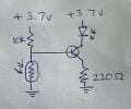
• 1kΩ (base resistor for transistor) then tried 220 as diagram
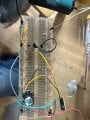
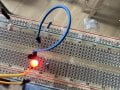
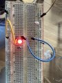
I have tried several diagrams found on the internet, using the attached diagram the led (just a 5mm red led for testing) was lit and covering ldr made no difference. I then tried changing the 10k resistor for a 1k resistor. I also asked AI which told me to switch the fixed resistor and ldr ( so v+ ldr fixed resistor to ground. This sort of worked with led going off in very bright light but on in ambient light. Changing resistor values did not help it was still on in ambient light.
As I am sure is clear by now I am a beginner and this was supposed to be a fun project with the kids and is now a life mission
Thanks
My components are
1. LiitoKala NCR18650B 3.7V 3400mAh Li-ion protected battery
2. CN3791 MPPT Solar Charger (for single-cell Li-ion, with 9V version)
3. 9V 2W Solar Panel
4. 1W 3V High Power White LED (mounted on a star heatsink)
5. LDO6AJSA (30-1500MA Adjustable Constant Current LED Driver DC 3.3V 3.7V 4.2V 5V PWM Control Board Buck Power module EGBO) pwm pin has been connected to vin
6. Photoresistor (LDR) resistance dark 9k ohms resistance light 250 ohms
7. NPN Transistor ( 2N2222. Ebc )
8. Resistors: I have a selection but started with
• 10kΩ (LDR voltage divider)
• 1kΩ (base resistor for transistor) then tried 220 as diagram
I have tried several diagrams found on the internet, using the attached diagram the led (just a 5mm red led for testing) was lit and covering ldr made no difference. I then tried changing the 10k resistor for a 1k resistor. I also asked AI which told me to switch the fixed resistor and ldr ( so v+ ldr fixed resistor to ground. This sort of worked with led going off in very bright light but on in ambient light. Changing resistor values did not help it was still on in ambient light.
As I am sure is clear by now I am a beginner and this was supposed to be a fun project with the kids and is now a life mission
Thanks
Attachments
-
 1.5 MB Views: 23