Facebook
 Google
 GitHub
 Linkedin
Hi
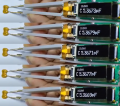
It is very likely that a worthy competitor to the LCR Pro1Plus may appear soon.
https://www.eevblog.com/forum/testgear/design-a-new-precision-lcr-tweezers/
It is very likely that a worthy competitor to the LCR Pro1Plus may appear soon.
https://www.eevblog.com/forum/testgear/design-a-new-precision-lcr-tweezers/