 Facebook
 Google
 GitHub
 Linkedin
Hi, I am designing an LC filter to go on the 24 Vac input power lines before the rectifier and switching regulator to filter out noise.
With a typical LC filter though, the inductor is in series with only on one line of the 24Vac. But it seems that noise could get through on the other line. Will it have the same response if I put a series inductor on both lines and the parallel capacitor after that (see attached picture)? I'm getting different results in LTSpice when I simulate that, but it also depends on where I put the ground in the simulation. If I put the ground on the lower side of the AC voltage source, then I get weird results. If I put the ground at the output of the circuit on the bottom of the load, then I get more reasonable results. But I get different results with 1 or 2 inductors (either 1 on 1 line or 1 on both lines).
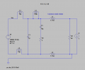
In the attached schematic, L3 and C1 form the typical LC filter. But to filter noise out on the bottom line of the AC voltage source, I put in L5. L1 and L2 are just a common mode choke. C3 and R1 are for damping at resonant frequency. L4 is not used (shorted out). I get reasonable results with the GND where it is in the picture. When I move it to the lower terminal (-) of the AC voltage source, then I get strange results (frequency response).
Where should I put the ground and should I only put L3 in or both L3 and L5 to filter out line noise?
Thanks.
With a typical LC filter though, the inductor is in series with only on one line of the 24Vac. But it seems that noise could get through on the other line. Will it have the same response if I put a series inductor on both lines and the parallel capacitor after that (see attached picture)? I'm getting different results in LTSpice when I simulate that, but it also depends on where I put the ground in the simulation. If I put the ground on the lower side of the AC voltage source, then I get weird results. If I put the ground at the output of the circuit on the bottom of the load, then I get more reasonable results. But I get different results with 1 or 2 inductors (either 1 on 1 line or 1 on both lines).
In the attached schematic, L3 and C1 form the typical LC filter. But to filter noise out on the bottom line of the AC voltage source, I put in L5. L1 and L2 are just a common mode choke. C3 and R1 are for damping at resonant frequency. L4 is not used (shorted out). I get reasonable results with the GND where it is in the picture. When I move it to the lower terminal (-) of the AC voltage source, then I get strange results (frequency response).
Where should I put the ground and should I only put L3 in or both L3 and L5 to filter out line noise?
Thanks.
Attachments
-
 14.8 KB Views: 63


