 Facebook
 Google
 GitHub
 Linkedin
I am unsure how to latch a motor into the forward position using a N/O push button, and unlatch while also latching into reverse using the temporary output of an object sensor (I'm using OPB715-716-717-718). I would then like to unlatch the motor from reverse and have it be off using another object sensor (of the same kind). I attached a picture of the H-Bridge design I used to make my circuit, if that helps with anything.
Attachments
-
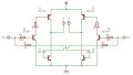 18.2 KB Views: 18


