Laser Driver

Thread Starter

Rahul@singh01

Joined Sep 30, 2024
5
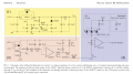
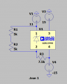
Hi, I’m working on a laser driver circuit based on the conventional Librecht-Hall design, but I’m encountering an issue with the voltage regulation section using the LM399. I’m not achieving the expected voltage drop of 6.95 V. When I substitute the LM399 with a zener diode, it functions correctly. Can anyone help identify what I might be doing wrong? I've attached the LTSpice simulation, where I used the ADR1399H, which provides a drop of 7.05 V instead of the desired 6.95 V. I’ve also included the standard driver circuit for reference.
 

Attachments

Thread Starter

Rahul@singh01

Joined Sep 30, 2024
5
Why do you have R1 and R2 in there? They seem to be defeating the purpose.
Hi,
I need to change the set voltage to change the current in the circuit. That's why, I'm using a potentiometer for it. Here, I'm trying to vary the voltage between 11V and 7.05V(voltage drop across ADR1399h. But, I'm not able to vary it.
 

wayneh

Joined Sep 9, 2010
18,087
In other words, you have two current paths in parallel, R1 and R2, and the internal zener. The data sheet says the zener operates in the range of 0.5-10mA.

The drop across R3 is (11 - 7.05) - (-15) = 22.05V. The current must therefore be 22.05V/7500Ω = 2.94mA.

The drop across both U1 and R1+ R2 = 7.05V and so the current in the resistors is 7.05/(10kΩ) = 0.07mA

Is this homework?
 

Thread Starter

Rahul@singh01

Joined Sep 30, 2024
5
In other words, you have two current paths in parallel, R1 and R2, and the internal zener. The data sheet says the zener operates in the range of 0.5-10mA.

The drop across R3 is (11 - 7.05) - (-15) = 22.05V. The current must therefore be 22.05V/7500Ω = 2.94mA.

The drop across both U1 and R1+ R2 = 7.05V and so the current in the resistors is 7.05/(10kΩ) = 0.07mA

Is this homework?
Hi,
Thanks for explaining it. I have just one vague question, in the original design attached here, they are using the same voltages and resistors in the ckt. Please correct me if I'm wrong, Is it because there is one more path attached to it via FET?
To make it work, which one would be better: reduce the regulated voltage(11V) or decrease the resistance pair(R1,R2)?
Yes, I'm making this circuit for my project work. I'm not exactly from the field, so I'm sorry if these questions seem silly.
 

Thread Starter

Rahul@singh01

Joined Sep 30, 2024
5
In other words, you have two current paths in parallel, R1 and R2, and the internal zener. The data sheet says the zener operates in the range of 0.5-10mA.

The drop across R3 is (11 - 7.05) - (-15) = 22.05V. The current must therefore be 22.05V/7500Ω = 2.94mA.

The drop across both U1 and R1+ R2 = 7.05V and so the current in the resistors is 7.05/(10kΩ) = 0.07mA

Is this homework?
Hi,
I checked the simulation. Initially, current flowing through R3 via calcualtion should be (11 - 7.05) - (-15)/7.5k = 2.52mA. But, in simulation, I'm getting 3.55mA.
And secondly, current in resistor is 0.705/(10kΩ) = 0.07mA. I'm not getting a voltage drop of 7 across zener instead i'm getting a voltage of around 11.7V. Please can you help in resolving it.
 
Top