 Facebook
 Google
 GitHub
 Linkedin
Hello
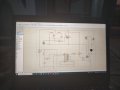
This circuit switch between two outputs and reset
I mean one click for lower button turn on the lamp, another click turn off different lamp, another click turn off both
I'm fine with this process, as I've already simulated and it work

My problem here, that I need control the lamp brightness with buttons, " the upper right and left",
The control work, and the voltage drops across the lamp when dimming, but when Release the button, the voltage start increase again across the lamp slowly and lamp start shine again
I've tried different capacitors, but same issue, only time change but not solve the problem
When simulate the irfz44n circuit alone, it work perfect,

when merge with 4017 circuit problem happens
How can I adjust the lamp dimming, and prevent capacitor discharge after button release?
This circuit switch between two outputs and reset
I mean one click for lower button turn on the lamp, another click turn off different lamp, another click turn off both
I'm fine with this process, as I've already simulated and it work
My problem here, that I need control the lamp brightness with buttons, " the upper right and left",
The control work, and the voltage drops across the lamp when dimming, but when Release the button, the voltage start increase again across the lamp slowly and lamp start shine again
I've tried different capacitors, but same issue, only time change but not solve the problem
When simulate the irfz44n circuit alone, it work perfect,
when merge with 4017 circuit problem happens
How can I adjust the lamp dimming, and prevent capacitor discharge after button release?
Attachments
-
 3.6 MB Views: 6


