 Facebook
 Google
 GitHub
 Linkedin
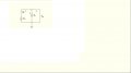
Using the KVL Mesh Current Method from the AAC e-textbooks.
The loop direction should tell you which way the current is flowing.
ie positive current: right direction. Negative current means re-draw arrow.
But I get a positive current from either direction for the loops:
Loop1
12V - R2I1 - 3.3V = 0
I1 = 17 mA
Loop1 (drawn other way)
-12V + 3.3V + R2I1 = 0
I1 = 17 mA
Where am I going wrong?
Attachments
-
 46.8 KB Views: 66
")


