KeyPad with Circuit Wizard

Thread Starter

MadmanW

Joined Feb 25, 2015
4
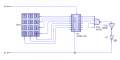
I starting an electronics project where I plan to build a simple alarm system where you can turn it off (once activated) using a keypad. I have created the circuit in circuit wizard and the flowchart seems to be working but I do not know how the keypad works so the micro chip is not reading the inputs from it.

Please can someone.... anyone who has an idea about keypads in circuit wizard help me.


Thank You in advance.
 

djsfantasi

Joined Apr 11, 2010
9,163
You would program the Genie to individually raise the pin associated with each row to a high level, while leaving the other rows at a low level. Then scan the three column pins for a high signal. The intersection of the row and column that are high defines which button is pressed. Warning, this simple approach does not account for multiple buttons pressed.
 

Thread Starter

MadmanW

Joined Feb 25, 2015
4
You would program the Genie to individually raise the pin associated with each row to a high level, while leaving the other rows at a low level. Then scan the three column pins for a high signal. The intersection of the row and column that are high defines which button is pressed. Warning, this simple approach does not account for multiple buttons pressed.
I think I understand what you are saying but when I press buttons on the keypad I am getting no response from the chip.
(note changed the pin numbers from the pic posted above).

upload_2015-2-25_19-6-45.png

Thank you for the speedy response
 

djsfantasi

Joined Apr 11, 2010
9,163
You're testing if D1 & D7 are on in the beginning of you flowchart. What you need to do is SET D1 high and see if D7 goes high. A keypad button connects a row to a column at the intersection. It does not change the output of a tow and column. Maybe this diagram will help
image.jpg
 
Top