KCL - Current Division Assistance

Thread Starter

10th&Bennett

Joined Apr 15, 2018
27
Greetings all again -

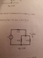
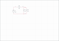
I'm trying to refresh KCL now. Referring to the diagram, I am trying to find the Current source value. Please note that the current source is not really 0 V, but I had to put a value in for Multisim. The only information I am given are the resistance values as shown, and (not shown, sorry) is the current value at the top of the node to the right of R3 is 4 Amps. The answer in the book for the current source is 6 amps.

Of course I am stuck yet again, but let me put the steps I did.

So I took that top node and thought that the current going into the node is equal to the current going out. So, I called the top of the node I3, and the left side is I1 (where R1 is 4 Ohms), and the right side is I2 (where R2 is 2 Ohms). So, I3 = I1+I2.

So with this part I did current division to find I1 and I2. For I1 = ((R2)/(R1+R2))*(I3) = 4/3 A. For I2 = ((R1)/(R1+R2))*(I3) = 8/3 Amps. These answers make sense since (a) I1+I2 = I3, and (b) the I2 value is higher in amperage due to lower resistance. Ok, so I am confident in that part.

Now, the next step I am not sure of. I know that R1 and R2 are in parallel, which Req in that case would be (4*2)/(4+2) = 8/6 = 4/3 Ohms.

But if I do current division with that, such that ((R3)/(R3 + Req) * (I3) = 3.15 Amps, and I know that is *not* right.

Any hints on the next step please? Please exclude Norton's/Thevinin's - I am not there yet.

Again, I am doing this for self-study.

Thanks!
 

Attachments

WBahn

Joined Mar 31, 2012
30,045
What do you mean by "the top of the node to the right of R3"?

The only way I can interpret that is as follows:

Prob2.png

But that would make I1 = 4 A.

The interpretation that would make the answer 6 A would be:

Prob3.png

But I don't see how this can be described as being "the top" of the node.

So which do you mean?

Annotated schematics are the language of electronics. Please try to start using them.
 

dl324

Joined Mar 30, 2015
16,909
It is the second figure you presented.
This is how I interpreted your description:
1600297844912.png
That's the only way this makes sense.
So with this part I did current division to find I1 and I2. For I1 = ((R2)/(R1+R2))*(I3) = 4/3 A. For I2 = ((R1)/(R1+R2))*(I3) = 8/3 Amps. These answers make sense since (a) I1+I2 = I3
EDIT: You should learn how to use Latex for more readable equations:
\(I_1 = I_3*\frac{R2}{R1+R2}=4A*\frac{2\Omega}{6\Omega}=\frac{4}{3}A\)
 
Last edited:

WBahn

Joined Mar 31, 2012
30,045
Yes my fault @WBahn. Long day but not an excuse. It is the second figure you presented.
If you aren't in a position to provide the diagram and must give a verbal description, then one way to have done it here would have been to say that it is given that the current flowing downward through R2 is 4 A.

If R2 is 2 Ω and there are 4 A flowing in it, what is the voltage across R2?

If you have the voltage across R2, what is the voltage across R1?

If you know the voltage across R1 and that R1 is 4 Ω, what is the current flowing in R1?

If you know the current in R1 and R2, what is the current flowing in R3?

If you know the current if R3, what is the current in the current supply?

Do you see the process? Take what you know, and see what additional piece of information you can glean from it. Is the a voltage, a current, or a resistance than is currently unknown that we can make a known? Then just keep repeating the process over and over until we have turned the unknown we care about into a known.
 

WBahn

Joined Mar 31, 2012
30,045
So with this part I did current division to find I1 and I2. For I1 = ((R2)/(R1+R2))*(I3) = 4/3 A. For I2 = ((R1)/(R1+R2))*(I3) = 8/3 Amps. These answers make sense since (a) I1+I2 = I3, and (b) the I2 value is higher in amperage due to lower resistance. Ok, so I am confident in that part.
You are making a very common mistake in that you are just throwing an equation at a problem without understanding what that equation does -- and does not -- mean.

Ix = Io * [Ry / (Rx + Ry)]

You can't just pick any current and call it Io. Io is the sum of the currents flowing in the two parallel resistors Rx and Ry. In your case, that is your unknown current.

If you ponder this just a little bit, you CAN use this equation to solve directly for the source current.

Here's a good strategy for you at this stage of your efforts -- don't use any equation that you can't derive from the fundamentals, which for you right now is KVL, KCL, and Ohm's Law.

You can't use the current divider formula until you understand it well enough that you can confidently pull out a piece of paper and a pen and derive it without referring to anything else. The same with the formula for calculating the effective resistance of two resistors in series and also two resistors in parallel. You can't just claim that the total resistance of two resistors in series is the sum of the two resistances, you have to be able to prove that this is correct.

Only once you can do that for a given formula can you add that formula to the tool box alongside KVL, KCL, Ohm's Law and use it in the future without re-deriving it.
 

Thread Starter

10th&Bennett

Joined Apr 15, 2018
27
If R2 is 2 Ω and there are 4 A flowing in it, what is the voltage across R2?

It would be 8 V. (2 Ω * 4 A)

If you have the voltage across R2, what is the voltage across R1?

Full disclosure, I do not know.
This is honestly where I get confused. Is this where we would combine them because they are in parallel?


And this is why I feel like a complete idiot asking these questions because I get stuck on something that is so simple. I am sorry.
 

Thread Starter

10th&Bennett

Joined Apr 15, 2018
27
Ok, with KVL, here's my approach. Voltage around a loop has to be equal to zero from yesterday's lesson. I'm only doing the loop that has R1 and R2 for starters.

So, going clockwise, the KVL loop equation would be (2 Ω * 4 A) + I(4 Ω) = 0

In order for that equation to be true, I would have to be -2A, such that 8V - 8V equals 0.

But at this point, I'm more than likely wrong.
 

dl324

Joined Mar 30, 2015
16,909
Ok, with KVL, here's my approach. Voltage around a loop has to be equal to zero from yesterday's lesson. I'm only doing the loop that has R1 and R2 for starters.
Whether you use Req or R1||R2, you only have 3 nodes. Since R1 and R2 have connections to the same nodes, what does that tell you about the voltages across them?

EDIT: Using your loop that only has R1 and R2, what did that tell you about the voltages across the resistors?
 
Last edited:

Thread Starter

10th&Bennett

Joined Apr 15, 2018
27
Supposedly that voltage is equal across all components in parallel. That is coming from this forum (Chapter 5 in AAC).

But Req would be 4/3 Ohms, and 4 Amps into that would be 5.333 Volts from V=IR.
1600307975969.png
 

WBahn

Joined Mar 31, 2012
30,045
If R2 is 2 Ω and there are 4 A flowing in it, what is the voltage across R2?

It would be 8 V. (2 Ω * 4 A)

If you have the voltage across R2, what is the voltage across R1?

Full disclosure, I do not know.
This is honestly where I get confused. Is this where we would combine them because they are in parallel?


And this is why I feel like a complete idiot asking these questions because I get stuck on something that is so simple. I am sorry.
You can't get past the point where you are getting stuck unless you are willing to ask.

By definition, two components are in parallel IF and ONLY IF they have the same voltage across them.

So, if two resistors are in parallel and we know that one of them has 8 V across it, what is the voltage across the other one?
 

WBahn

Joined Mar 31, 2012
30,045
Ok, with KVL, here's my approach. Voltage around a loop has to be equal to zero from yesterday's lesson. I'm only doing the loop that has R1 and R2 for starters.

So, going clockwise, the KVL loop equation would be (2 Ω * 4 A) + I(4 Ω) = 0

In order for that equation to be true, I would have to be -2A, such that 8V - 8V equals 0.

But at this point, I'm more than likely wrong.
What direction is that current 'I' flowing in the 4 Ω resistor?
 

WBahn

Joined Mar 31, 2012
30,045
Supposedly that voltage is equal across all components in parallel. That is coming from this forum (Chapter 5 in AAC).

But Req would be 4/3 Ohms, and 4 Amps into that would be 5.333 Volts from V=IR.
View attachment 217412

Track your units! You got a number = a number = a resistance.

4 A is what is flowing into JUST R2. There is also current flowing in R1. The current flowing in the parallel equivalent is the total of the current flowing in R1 and R2.

You ALREADY know that the voltage across them is 8 V.
 
Top