K Type Thermocouple Cold Junction Compensation and Amplifier to ADC

Thread Starter

rennie1080

Joined Apr 10, 2017
52
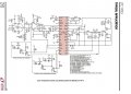
I try to build a thermocouple design.I have read sources about thermocouple, cold junction compensators and some IC datasheet.I'm making a thermocouple based temperature controller. My aim is to detect the range of -200C to +600 C.The thermocouple voltage is measured by using cold junction compensation IC LT1025 and precision opamp LT1050.Aim for accuracy is 0.1K by using K type . LT1025 have 10mV/C. I will measure the temperature of heater and chiller by using thermocouple. Heater will be heated up to 600C degree and temperature of chiller will go down to -200C degree.But most of products dont mention very high or very low temperature issues. But in LT1025 datasheet, it says that it is convenient range of 0C to 50C and can enhance range by changing resistors.While I search convenient components to use in cold junction compensator and precision zero drift amplifier for output.Could you advise a design and components to achieve the range by details? Can you advise other IC,compensator and amplifier to build accurate thermocouple?
 

ebeowulf17

Joined Aug 12, 2014
3,307
I've used the AD8485 in a few applications with good results.

http://www.analog.com/media/en/technical-documentation/data-sheets/AD8494_8495_8496_8497.pdf

https://www.adafruit.com/product/1778

With the AD8495, the temperature range you can measure is the full range of a type k thermocouple. The 0-50C limitation is on the ambient temperature where the chip is. So, you want the thermocouple to be in the hot or cold thing that you're measuring, and you want the 8495 to be somewhere else, between 0-50C. I imagine it's the same situation with your chip as well, but I haven't checked.

That said, your accuracy requirement is beyond the intrinsic accuracy of any of the parts involved. You would need to do a lot of calibration and confirmation to make any attempt at such extreme accuracy at such extreme temperatures. If you just need that level of resolution, but absolute accuracy can be a little looser, that's much easier, but getting fractions of a degree of accuracy is difficult even near room temperature, and far more difficult at the extremes.
 

Reloadron

Joined Jan 15, 2015
7,850
Just looking at the limits of error for a Type K thermocouple:
Type K:
MAXIMUM TEMPERATURE RANGE
Thermocouple Grade
– 328 to 2282°F
– 200 to 1250°C
Extension Grade
32 to 392°F
0 to 200°C
LIMITS OF ERROR
(Whichever is greater)
Standard: 2.2°C or 0.75% Above 0°C
2.2°C or 2.0% Below 0°C
Special: 1.1°C or 0.4%

Take note of the limits of error for both Standard Grade and Special Grade. With that in mind you can, depending on your location, purchase calibrated thermocouples where you call out the cardinal points and a supplier will run a calibration curve for you. For example -200C to 600C you could request 100C cardinal points which would give you 9 points and you pay by the point for the metrology services. A thermocouple at -200 C may be off by -1.0 C and the same thermocouple at 600 C may be +2 C. That error needs considered depending on how accurate you wish your measurement plane to be.

Next and taken from ebeowulf17's link:
"The AD8494/AD8495/AD8496/AD8497 allow a wide variety of supply voltages. With a 5 V single supply, the 5 mV/°C output allows the devices to cover nearly 1000 degrees of a thermocouple’s temperature range".
So whatever you choose to use for an A/D converter it needs to have great enough resolution to resolve the 5mV/C or whatever you have.

That said, your accuracy requirement is beyond the intrinsic accuracy of any of the parts involved. You would need to do a lot of calibration and confirmation to make any attempt at such extreme accuracy at such extreme temperatures. If you just need that level of resolution, but absolute accuracy can be a little looser, that's much easier, but getting fractions of a degree of accuracy is difficult even near room temperature, and far more difficult at the extremes.
That is exactly what this works out to.

Ron
 

Thread Starter

rennie1080

Joined Apr 10, 2017
52
Thanks for your answers. By using applicaiton design on AD8494 datasheet, How much accuracy can the circuit achieve for K type?
And also The thermocouple circuit will be in the main circuit board. I will be careful about IC temperature range.

I will design TEC controller by using LTC1923. In the datasheet of LTC1923( attached to the post), NTC is used. I want to design alternative of NTC by using thermocouple. How can I adapt thermocouple to the design in LTC1923 ?
 

Attachments

Reloadron

Joined Jan 15, 2015
7,850
If we look at the drawing on page 1 of the LTC1923 data sheet we can see how things fit together. The LTC® 1658 is a single supply, rail-to-rail voltage output, 14-bit digital-to-analog converter (DAC). This is where the set point is originated as a voltage level. The LTC1658 analog voltage value is passed on to the inverting input of a LTC2053 Instrumentation Amplifier while the non-inverting input of that same IA is the result of a voltage divider comprised of a 10 K Ohm NTC Thermistor. The resulting output of the LTC2053 IA is the control input to the LTC1923 pulse width modulator intended for thermoelectric cooler (TEC) or heater applications requiring either unidirectional or bidirectional drive circuits. That is how things work in a nutshell. Now knowing that and how things work together you should be able to figure the non-inverting voltages into the IA based on the temperature using the !) K NTC Thermistor chart linked to.

If you read through all of the data for the LTC1923 you will see reference to both thermistor and PRT (Platinum Resistance Thermometer). When we want high, very high accuracy in temperature measurement we look to the more expensive PRT sensors. I posted earlier the limits you can expect using a type K thermocouple. The overall uncertainty of any temperature measurement plane is the sum of all of the uncertainties in the system. That is as good as it gets. If you want to substitute a Type K thermocouple in your design, look at the Type K tables and scale your voltage into the IA accordingly.

Ron
 

Thread Starter

rennie1080

Joined Apr 10, 2017
52
If I design a thermocouple circuit by using AD8495 and the output voltage of thermocouple circuit is suitable to IA and LTC1923, Can I replace NTC by thermocouple circuit directly (attached circuit) ? Or need to scale utterly voltage for suiting up with NTC output voltage ?


Reloadron

Joined Jan 15, 2015
7,850
In the original example circuit Vref is tied to the ADC and is on the top of a 10K precision 0.1% resistor which is in series with the NTC sensor. I explained it was a voltage divider network and you may want to note would reduce the current through the NTC to reduce self heating. If we are not using a thermistor we don't need or use that resistor.

You call out -200 to 600 Degrees C (-328 to 1112 F.) so since you have a temperature below zero C make sure you read Driving the Reference Pin The AD849x comes with a reference pin, which can be used to offset the output voltage. This is particularly useful when reading a negative temperature in a single-supply system.

As I mentioned earlier make sure you scale things accordingly.

Can I replace NTC by thermocouple circuit directly (attached circuit) ? Or need to scale utterly voltage for suiting up with NTC output voltage ?
You need to read and understand all of the data sheets.

Ron
 

ebeowulf17

Joined Aug 12, 2014
3,307
As a side note, is the plan to generate these temperatures just with the TEC that you're working on a control circuit for? I ask because I was under the impression that TECs had a limited range of heating and cooling they could provide, and it's nowhere near enough to deliver those temps if they're starting at room temp.

I could be way off on this - I have no personal experience with them, I'm just recalling what I've heard others discuss. If you know otherwise, or if that wasn't the plan to begin with, disregard this comment.
 

Reloadron

Joined Jan 15, 2015
7,850
As a side note, is the plan to generate these temperatures just with the TEC that you're working on a control circuit for? I ask because I was under the impression that TECs had a limited range of heating and cooling they could provide, and it's nowhere near enough to deliver those temps if they're starting at room temp.

I could be way off on this - I have no personal experience with them, I'm just recalling what I've heard others discuss. If you know otherwise, or if that wasn't the plan to begin with, disregard this comment.
I was wondering about that? Also TECs are not very fast in their response and my read has been that they really don't fare well with PWM. Very good point there ebeowulf17.

Ron
 

Thread Starter

rennie1080

Joined Apr 10, 2017
52
I plan to use both peltier and heater. Heater will be heated up to 600C and by using liquid nitrogen , the chamber will cool down to -196C degree. Peltier will be an option for the narrower range.
 

Reloadron

Joined Jan 15, 2015
7,850
So you are using a thermal chamber to do thermal shock test? While I don't know all the details I don't see a TEC as a good choice. You also want a controller with a form of Aux Out to control a LN solenoid valve. The chambers I worked with and controlled over the years used electric heater elements to make hot and then we kicked in a few refrigeration compressors along with open a LN solenoid for rapid temperature pull down. You also need to watch the transition carefully least you fracture anything, including the chamber.

Your best bet would likely be to buy a controller which allows storing a profile and has aux outputs. However, it is your project and your choice.

Ron
 

Thread Starter

rennie1080

Joined Apr 10, 2017
52

The system is like system in video. I will control the temperature with controller including LT1923, thermocouple and alternatively pt100 or NTC. There is a specimen in the head. Characteristic of specimen will be observed in low and high temperature. Low temperature will be achieved by using liquid nitrogen an high temperature will be achieved by using heater. But I want to add peltier for alternative narrow temperature range. LTC1923 is absolutely suitable for heater. The output of thermocouple will go to DAC in LTC1923 system. I think one connection from output directly can connect to ADC for independecy from LTC1923 to measure low temperature when using liquid nitrogen.
 

Thread Starter

rennie1080

Joined Apr 10, 2017
52
Thank you for your answers Reloadronç If you were me, what do you do ? When you consider of the system I told, how do you design the temperature, heating and cooling system ?
 

Reloadron

Joined Jan 15, 2015
7,850
It has been decades since I actually had to "design" a temperature control system. During my later years I was fortunate in that I was able to buy turn key off the shelf controllers.

The beginning of any temperature control system starts with the choice of temperature sensor so we look at range and you mentioned -200 to 400 degrees C which is a wide range and rules out sensors like a thermistor. Next I consider allowable uncertainty, how accurate do we need to be? If I choose a thermocouple I need to consider the type and if in a sheath the exposed environment? Actual junction size because the wire gauge used to make the thermocouple determines not just maximum temperature but also the response time. How fast do I need my thermocouple to respond? Note these are both Type K thermocouples, obviously the small junction will have a much faster response but would not be suited for use in a furnace.


Once I determine which is the best sensor then I need to consider signal conditioning. Using an over the counter controller the controller would do the signal conditioning but if I am designing my own then signal conditioning rest with me. I liked using what we called temperature transmitters similar to the below image.


These are widely manufactured and distributed with newer versions allowing programming for sensor type and also range. They provide a 4 to 20 mA output also. Here are some examples of the Inor temperature transmitters pictured above. I liked using the INOR IPAQ-H quite a bit. With only a 24 VDC power supply I get a 4 to 20 mA loop current out and pass it through a 250 Ohm precision resistor for a 1 to 5 VDC level. Now my programmed range is equal to 1 to 5 VDC. Using your -200 to 600 C it would be -200 = 1.0 volt and 600 = 5.0 volts. We can say a span of 800 degrees = 4 volts or 4/800 = 5 mV per degree C.

At that point I just run the voltage into an A/D converter and use my software. Years ago, on the side, I helped a friend with a computer forum doing some hardware test involving temperature. Here is an example of using 4 temperature transmitters.


I fabricated 4 Type J Thermocouples.


I used an inexpensive A/D data acquisition module.


Wrote a simple program.


If I were you I would look for a temperature transmitter, set it up so you get 1 to 5 volts using a 250 Ohm resistor in the 4 to 20 mA loop. I would use the programmable D/A we looked at and the controller we looked at. If you want to record data then there are more options as we frequently recorded the temperature data for thermal test.

Ron
 

Thread Starter

rennie1080

Joined Apr 10, 2017
52
Thank you for your answers. I want to learn something about thermocouple. My design's aim is to build fast response thermocouple. I examine datasheets of max 31856-31855 and ad8495. Temperature Conversion Time respectively are 170 ms, 70 ms and 40 ms. Their speed is not sufficient for the application. Could you advise some IC or solution to make the system response faster ?
 

Reloadron

Joined Jan 15, 2015
7,850
I think it would be wise to start at the beginning. While it is nice to know the temperature conversion times of the listed devices they alone do not tell the full story. I would start with the actual thermocouple “Time Constant” or “Response Time” which is defined as the time required to reach 63.2% of an instantaneous temperature change. You may want to give Thermocouple Response Time from Omega Engineering a read through. Frequently depending on exactly what you wish to do the thermocouple will be the slowest responding device in a measurement plane. Before you even worry about conversion time you need to find a thermocouple which will respond fast enough for your needs over a given span of temperatures.

Ron
 

ebeowulf17

Joined Aug 12, 2014
3,307
Where are you getting 40mS for the AD8495?

There's no conversion being done in that chip. It's simply an amplifier with cold junction compensation. The conversion time would be determined by whatever ADC you use to digitize the analog signal coming out of the AD8495.

The only limit presented by the chip itself is 40uS (1000 times faster) settling time, and that's spec'd at a 4V output swing, which is huge. Response time of the thermocouple itself is bound to be much more of a limiting factor.
 

Thread Starter

rennie1080

Joined Apr 10, 2017
52
Ron and ebeowulf17 thank you for your answers and patients. I misunderstood about analog compensator. So what is the differences between conversion time and response time for thermocouples? I want to build a thermocouple circuit that measure temperature and its measurement speed is important. Where do I can begin to build it? Firstly I choose thermocouple that response fast. Then I can use compensator and adc .
 
Top