K thermocouple values not stable (Max31855) / Information on Relay

Thread Starter

Kadav

Joined May 11, 2018
158
A glass of ice water may work. But there will be temperature gradients in it. An insulated glass, thermos, or foam cup might be better.
@jpanhalt

I did not manage to get ICE because its summer and every one is taking the ice in my place , but i stuck the end of the thermocouple in a sponge for washing dishes
1595957230650.png

and here is the result

1595956586175.png
i don't know if we can call it stable

another thing is that the module is made up of level shifter circuit , so i guess we must put it in a 3.3v input instead of a 5v (which i had powered it to 5v ) i don't know it that changes something or not !! as it is on the Datasheet of the module

How accurate is m info
 

jpanhalt

Joined Jan 18, 2008
11,087
Good enough for me. Good work.

See, air currents matter when you have a very responsive way to measure temperature. As I mentioned earlier, I could walk by the MAX31856, and it would show my presence (Winter, room temp about 20°C)

Yes, you need level shifters if the rest of the circuit is 5 V. They can be simple.
 

Thread Starter

Kadav

Joined May 11, 2018
158
Good enough for me. Good work.

See, air currents matter when you have a very responsive way to measure temperature. As I mentioned earlier, I could walk by the MAX31856, and it would show my presence (Winter, room temp about 20°C)

Yes, you need level shifters if the rest of the circuit is 5 V. They can be simple.
@jpanhalt

Can you please explain me what a level shifter is ?
I understand what logic levels are which in my mind is 1 and 0 but what does level shifter means .

I am not sure but i think that we use 3v because there is a level shifter circuit that brings the 3v to 5v . is it accurate or not ?

This is from what i read from the internet but it is not accurate either in my mind ......

Thanks
 

MrSoftware

Joined Oct 29, 2013
2,273
Level shifters: Disclaimer: there exceptions, always read the datasheets.
That said; different chips will have different logic levels. i.e. different voltages at which a 0 becomes a 1, and a 1 becomes a 0, and different maximum voltages on their logic pins. For various reasons, chips with different logic levels likely won't work well together. The solution is a level shifter, which will for example convert 3.3v logic to 5v, and 5v to 3.3v, allowing 2 devices with different logic voltage levels to work together. For example, if you wanted to use an ADC chip with 3.3V logic with your Arduino Uno, which has 5V logic, a level shifter is likely necessary. Often when you're in the R&D phase, it's cheaper and easier to use an off-the-shelf module than to make your own. Here are some cheapies on Amazon that worked for me for level shifting some some SPI signals between 3.3v and 5v: https://www.amazon.com/gp/product/B07LG646VS/ref=ppx_yo_dt_b_search_asin_title?ie=UTF8&psc=1
 
I found the Maxim thermocouple IC's not so great. Readings all over the place.

One problem is the IC floats the thermocouple and switches it during the test cycle. So it is very susceptible to common-mode noise. The THREE 10nF caps and two ferrite beads help for RFI, but do nothing for low frequency mains common-mode noise.

If OP's power supply circuit is not earth-grounded, which can be the case with wall-wart PSU, the IC will give wandering readings and sometimes trigger false fault flags, such as the stupid "TC short to Vcc".

So I am saying:
Earth-ground your power supply DC(-).
Do not let the thermocouple touch anything metal, such as oven grill.
Keep your cellphone far away from all thermocouple wiring.
Make sure the IC TC input has good filtering.

I add the input filter and problems went away. It's just the IC is extremely sensitive to EMI/RFI. Too much so for industrial use.
 

Thread Starter

Kadav

Joined May 11, 2018
158
NEW QUESTION

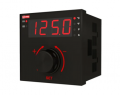
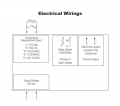
I m sorry but i don't want to create a new thread for this question but , i need to plug a 10W (5V 2A) heater on this Pid controller ( image below ) and it's Datasheet is as shown in the second image.

But it has 2 output relays

the first can connect to a 17@250 Vac and the second can connect at 10ma @17 Vdc

for my heater to work well when i use a variable power supply i connect and put (5vdc at 2A) then it heats first.

so should i connect it to the 1st or the second ( i feel like the 1st may burn it and the second may not heat it )

Please answer me may be with an explanation that will be fine .


1596034860701.png
1596034776712.png
 

jpanhalt

Joined Jan 18, 2008
11,087
Neither output meets your need of 5V @2 A DC per se; however, the second output is not for power, but is for driving a solid state relay. That (an SSR) should be able to control your heater with its current supply..

Did you notice that your new controller connects directly to the thermocouple?
 

Thread Starter

Kadav

Joined May 11, 2018
158
Neither output meets your need of 5V @2 A DC per se; however, the second output is not for power, but is for driving a solid state relay. That (an SSR) should be able to control your heater with its current supply..

Did you notice that your new controller connects directly to the thermocouple?
YEah , but i have to build a temperature PID system with arduino tooo , i am doing both of them at the same time
 
Last edited:

Thread Starter

Kadav

Joined May 11, 2018
158
Neither output meets your need of 5V @2 A DC per se; however, the second output is not for power, but is for driving a solid state relay. That (an SSR) should be able to control your heater with its current supply..

Did you notice that your new controller connects directly to the thermocouple?
@jpanhalt

Hello

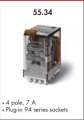
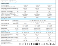
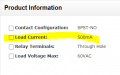
as you have seen i have a 10ma@17V maximum output and i am using this relay datasheet (General purpose relay 7A )

1596047227221.png

But i do not see its minimum switching current , is there a way to see it ?
and how can i find a relay that can allow my 10ma max output ?

Thanks

1596047474305.png


Or can i use a BJT to magnify the current ? can it be also a good idea ( i am trying it as i am asking )
 

jpanhalt

Joined Jan 18, 2008
11,087
The coil's rated DC power is 1W. V*A = W for DC (V*A = 1.5 for AC). Thus, @12V, you would expect about 83 mA. That is probably not a stringent requirement, but I doubt 10 mA will cut it. A bjt transistor or mosfet will work. If you use a bjt, be sure to check what maximum allowable base voltage is.
 

Thread Starter

Kadav

Joined May 11, 2018
158
The coil's rated DC power is 1W. V*A = W for DC (V*A = 1.5 for AC). Thus, @12V, you would expect about 83 mA. That is probably not a stringent requirement, but I doubt 10 mA will cut it. A bjt transistor or mosfet will work. If you use a bjt, be sure to check what maximum allowable base voltage is.
Ooooh ok that is what the 0.8 mean ?
The coil's rated DC power is 1W. V*A = W for DC (V*A = 1.5 for AC). Thus, @12V, you would expect about 83 mA. That is probably not a stringent requirement, but I doubt 10 mA will cut it. A bjt transistor or mosfet will work. If you use a bjt, be sure to check what maximum allowable base voltage is.
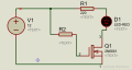
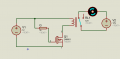
1596126261258.png
Can you please tell me what's wrong with a setting like this one ?

At first R2=0 then it did not work then put a 10K so that when the MOSFET is on the Vgs is not short circuited..
How does someone connnect a Mosfet with the same powersource ?
I know its basic but it's haunting me
 

jpanhalt

Joined Jan 18, 2008
11,087
Your 17 V/10 mA supply can't supply enough power. You need to use the 17 V/10 mA as a signal only on the gate. The relay will need another supply. (Assuming the LED is a substitute for the relay you want to use.)
 

Thread Starter

Kadav

Joined May 11, 2018
158
@jpanhalt yeah it replaces the the relay

But i am using a normal power supply of 30V 3A and it still doesn't work . something is wrong that i do not know ...

In simulation it works but on the actual board it doesn't ! but in simulation it works even when the +ve
is not at the gate it reads the negative as a value also...
Your 17 V/10 mA supply can't supply enough power. You need to use the 17 V/10 mA as a signal only on the gate. The relay will need another supply. (Assuming the LED is a substitute for the relay you want to use.)
I was using a 30V 3A power supply

But I have seen it!! it works

Before i had not put a resistor at the gate and it was creating a short circuit between the gate and the source i think ,
but i don't understand why because i think a MOSFET has an infinite resistor at the gate which is why we do not need to connect the resistor like we do on a base of a BJT
 

jpanhalt

Joined Jan 18, 2008
11,087
A supply of 17 V with a 1700 Ω will provide 10 mA. A 10 k resistor at R2 is much larger than it needs to be. Try a 1 k; if that doesn't work, 1.5 to 2 k.
 

Thread Starter

Kadav

Joined May 11, 2018
158
yeah it worked
with a 1k thanks
@jpanhalt
I realise that i finally need another voltage source to run the system after a relay, which i don't have. and the one i have is a contact relay not SSR which makes a lot of sound ..

1596133172281.png

Ofcaurse i finally realise that i need to buy a solid state relay , i looked on the internet and then i found this one
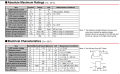
Mosfet relays and its datasheet is but its image of what i think is important is down below , so my question is can it work with my PID (10ma@17V)

if no, how can i find one that works and which specs did you use , if you can tell me ?

1596134462147.png
1596134937264.png
 

jpanhalt

Joined Jan 18, 2008
11,087
That's a mosfet version of an optocoupler. The maximum forward current is 50 mA. Your 10 mA will work, according to the second table. LED's are current devices. Be sure to add a resistor to limit the current.

R(on) is about 1Ω and it will switch 500 mA (constant). 1 A peak. Is that enough?
 

Thread Starter

Kadav

Joined May 11, 2018
158
That's a mosfet version of an optocoupler. The maximum forward current is 50 mA. Your 10 mA will work, according to the second table. LED's are current devices. Be sure to add a resistor to limit the current.

R(on) is about 1Ω and it will switch 500 mA (constant). 1 A peak. Is that enough?
Hii

Do you mean 1A for load current ? I need one that allows 2A of current to pass through
 
Top