ε = I·(r + R) = v + V -- where ε is EMF of the galvanic cell , r is the equivalent internal resistance of the galvanic cell , I is the current through the series circuit of battery and resistor R.
-- at your case --
ε = I·(r + Rꜱ + R) = v + u + V -- where Rꜱ is 100mΩ , u is the voltage drop at Rꜱ , which value must be pre-calibrated for different currents at different ambient , R includes the non-linear channel resistance of the MOSFET which also is T° dependent and current dependent . . . but also the r is dependent on SOC of the battery & rate of discharge of the battery & possible PWM/PFM frequency and duty
. . . basically you never mentioned what you hope to achieve with your experiment ???
It's not exactly an experiment. it is or will be a part of an even larger more insane project I have been working on for I could say since I was a teen and that would be true but the teen me had no chance of bringing it to life I at least have a chance to do it. and it's exactly what I want or will be.
I just remembered that AO3400 and AO3401 have been obsolete for a while now. The replacement for AO3400 is AOSS32334C. Specs for the replacement are better; except that threshold voltage increased by about 1V.
Where did you order from? I was tempted to buy a reel of each from AliExpress when they were end-of-lifed, but decided not to tempt fate.
ε = I·(r + R) = v + V -- where ε is EMF of the galvanic cell , r is the equivalent internal resistance of the galvanic cell , I is the current through the series circuit of battery and resistor R.
-- at your case --
ε = I·(r + Rꜱ + R) = v + u + V -- where Rꜱ is 100mΩ , u is the voltage drop at Rꜱ , which value must be pre-calibrated for different currents at different ambient , R includes the non-linear channel resistance of the MOSFET which also is T° dependent and current dependent . . . but also the r is dependent on SOC of the battery & rate of discharge of the battery & possible PWM/PFM frequency and duty
. . . basically you never mentioned what you hope to achieve with your experiment ???
I would call an 18650 cell with an internal resistance of 100+mohm an end of life cell. most that I have worked with have ranged between 30 and 50 mohm new off the shelf after a time of normal and sometimes heavy use that internal resistance can and does change it climbs at about the same rate as the capacity is lost. we made specialized cells for various mining and scientific power needs. some of those battery banks were expected to deliver on demand upwards of 300 amps and those we saw go on the bad side much quicker and there was little we could do about it. but that department was never my area we had smart engineers mostly working in that department my job for a couple tears was burning out 18650's and 21700 cells and report on my findings and suggestions for better battery packs for the heavy draw current battery banks. is 21700 better than 18650 for that purpose and which would offer better longevity. from then it was up to those smart engineers to take over and ahhm make it happen.
It should do what I want it to. I'll be using it in the 28-028 configuration with the hope of getting better than 24-0-24 after rectification and filtering. Use the 12 volt part for other projects within the case. Not looking forward to the cost of the caps though.
There isn't anything not working it does work as it's supposed to but I hesitate to state without a doubt till I have made it work and break a sweat as it were. I do not have anything in heat sinks they are coming in this week I hope along with my 150.00 mouser order. A lot of that order is restock though. But the heat sinks are coming from the far east and I can not be 100%sure that they will be in at the same time as my mouser order. sometimes weeks longer than expected. want to get it up and running. I am toying around with the TL431 and another reference zener I have to try to maybe get that a2.5 volts up a bit closer to the 2.8-2.9 I was shooting for. but If push comes to shove I'll just make it very close to 3 or the best I can and live with that. But your design is good and it does work.my inner 5 year old just likes to play with new toys. In addition I do not yet have the SMD ptype MOSFET yet that is in my mouser order. That will take me a day or so to get into safe containers I don't need them getting all staticky on me static free all the way with those things. Oh and sorry for all the questions but these MOSFETS are still new to me even though I have absorbed a lot of info on them I just want to be sure that I don't have it all backwards. My understanding of the P-type MOSFETS is that much like the PNP transistor the gate of the P-type must be of lower potential than the source of the MOSFET so given the P-type at the top of the 2 it must be in a constant on state till the battery reaches the reference voltage then it is pulled high by I assume the LM393 is that correct or have I got it all screwed up.
MOSFETS are still new to me even though I have absorbed a lot of info on them I just want to be sure that I don't have it all backwards. My understanding of the P-type MOSFETS is that much like the PNP transistor the gate of the P-type must be of lower potential than the source of the MOSFET so given the P-type at the top of the 2 it must be in a constant on state till the battery reaches the reference voltage then it is pulled high by I assume the LM393 is that correct or have I got it all screwed up.
You're correct in that P channel enhancement mode MOSFETs require a negative Vgs to turn on. I think that the Vgs(th) voltage can be specified for currents other than 250uA.
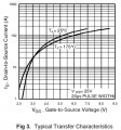
You need to be concerned about what Vgs is required for 0.1-2A. You get that from the curves for a typical device (of which a majority of devices will be):
This is for IRLZ44N. At a Vgs of 2.5V, it will conduct over 3A.
Since the LM393 is operating from a 9V supply, Vgs will be positive when the P channel MOSFET is turned off. That's okay because positive Vgs just tries to turn the device off harder.
Enhancement mode MOSFETs are much more common than depletion mode. In a depletion mode device, drain current flows at Vgs=0V. In the case of a P channel depletion mode MOSFET, making Vgs more negative turns the device on harder and making Vgs more positive decreases drain current.
You're correct in that P channel enhancement mode MOSFETs require a negative Vgs to turn on. I think that the Vgs(th) voltage can be specified for currents other than 250uA.
You need to be concerned about what Vgs is required for 0.1-2A. You get that from the curves for a typical device (of which a majority of devices will be): View attachment 368800
This is for IRLZ44N. At a Vgs of 2.5V, it will conduct over 3A.
Since the LM393 is operating from a 9V supply, Vgs will be positive when the P channel MOSFET is turned off. That's okay because positive Vgs just tries to turn the device off harder.
Enhancement mode MOSFETs are much more common than depletion mode. In a depletion mode device, drain current flows at Vgs=0V. In the case of a P channel depletion mode MOSFET, making Vgs more negative turns the device on harder and making Vgs more positive decreases drain current.
I have noticed with the MOSFET I have been working with. another educational endeavor. Sometime I learn better by testing and measuring. Only small LED loads at the moment but at about 1.5 volts at the gate the device turns on drawing only about 100 to 150uA but as soon as the gate hits about 2 volts there is 20mA or better and going up to 3 with this load made no real difference. So you mean I need to be concerned about that with the one that is controlling the Pot to vary the current. I have been thinking about that and I'm not sure I want to take it to 100ma I thought maybe 300ma would be a low enough current for slow discharge. then up to 2 do discharge rapidly. It will be tough to get the twist just right to precisely control that current. I have some digital brains coming in that will end up handling most of that. and a bunch of other tasks I have assigned to it. Maybe a bit of datalogging may as well earn it's keep.
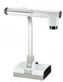
Can I assume the Elmo viewer is something you mount over your work and view it on your laptop. Is there any Lag at all. I wonder if I could employ an unused 4K webcam to do the same thing. But likely not I don't think it has the functions it would need like zoom. lacking that makes it about useless.
Alright I'll go ahead and take a look for that and see about getting one. Thank you. Well if you have an Elmo viewer and it costs so cheap you are lucky the ones that they have out now are 1400.00 I don't think that will work for me. the microscope I was looking at has it's own small screen and it can go to a pc monitor and the cost is only 249.00 and it's also 4K. Still seems the cheapest offering. will be a while yet I may have to save for a while or lay off the mouser orders for a while Then I could get it in a couple months.
I was looking on Amazon and aliexpress I never thought about ebay Well I guess I'll have a look there. I have no idea why I skipped that on as I usually look on all three of them. Thanks again for setting me straight.
i was reffering to a datasheet of a flat 700mAh Li-Ion cell as in an old cell-(not "smart-") phones . . . as i've not tested the 18650 myself i find the "proposed" ability to output 25A rather questionable . . .
i was reffering to a datasheet of a flat 700mAh Li-Ion cell as in an old cell-(not "smart-") phones . . . as i've not tested the 18650 myself i find the "proposed" ability to output 25A rather questionable . . .
They can pull something on the order of 100 or more amps when they are put into a battery bank. just the battery operated tools can pull 20A continuous and far more than 100A for short duration. Where I used to work made battery banks that pulled like in the order of 300A for very short duration. These were used by exploration geologists. these are the ones that would not last that long and I for 2 years tested every battery type we could get our hands on to find the battery type that would take that sort of current draw and last for more than 4 months. I finaly found just the right battery type. the newest 21700's could handle that much current continuously for about a year before the batteries internal resistance and therefor the capacity of the battery dropped to low. That was the problem with most of the batteries I had to test. except one type of 21700 battery. those are the ones now used to create the battery banks they are a tiny bit larger and a bit heavier but that is acceptable. the 18650 in a bank you would find in a hand tool pull initially about 100A and then settle down to a steady 5 amps. that was for a hand saw. the drills not so much but even they can pull 50A on startup. a single 18650 can take a steady 2A output for about an hour or so I hard drained the batteries individually at about 3A and they handle that quite well. but that is a hard drain. mostly I drained them at about 1A. We built a device to hold hundreds of 18650's and hundreds of 21700's each cell could be accessed drained and recharged individually or in banks of any size including ones that were output voltages of close to 120V DC. I was never talking single individual cell pulling 25A that would be impossible like I said 3A for a hard discharge of a single cell. but in banks the sky is the limit. but 700mAh is a very low for an 18650 cell when I got them they were in the area of between 2500mAh and 3300mAh when new after I had run a number of tests the internal resistance climbed above 100mOhms and battery capacity dropped to less than 1/2 of those numbers. but it was necessary for longevity tests at sometimes ridiculous draw currents. the cells you were testing were lithium polymer batteries that is usually what they put into cell phones and they have capacities in the area of 600 to 1200mAh and handle much lower steady current draws. that is a different type of battery chemistry than the jelly roll cells I worked with which are lithium ion cells.

 Facebook
 Google
 GitHub
 Linkedin
![20260624_214329[1].jpg](/data/attachments/356/356348-e6aa74f8f7dc217900d625dd4231c1e2.jpg) 651.5 KB Views: 2
651.5 KB Views: 2