JLH 1969 Class A power amp issue

Thread Starter

ACK303

Joined Mar 13, 2020
24
Hi everyone,

Looking for any suggestions please.

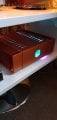
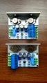
Built a JLH 1969 power on PCB's and all was well. Replaced the output caps and then it developed a hum. I wired all grounds which got rid of the hum.

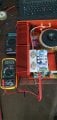
But now, I cannot get any current. The set up for the amplifier is half input voltage, DC midpoint (26v/2 = 13v) and then, adjusting KT2 trimpot to set current to 1.2amps.

One channel is perfect, 2nd channel reads full 28v at midpoint with 0amps in series with the power supply?

Any suggestions would be very much appreciated I'm missing the amp terribly.

Regards,

Adam
 

Attachments

Thread Starter

ACK303

Joined Mar 13, 2020
24
Hi Dodgydave,

That's the one, with a couple of trim pots and an led circuit in addition.

I'll double check TR1 (And other transistors) I did tighten the collector bolts up so maybe created a dry joint but I did resoldered them anyway. I'll try again....

Thanks for the response.
 

Audioguru again

Joined Oct 21, 2019
6,691
All that heat but only 6W of audio into an 8 ohm speaker?
I heat my home with a natural gas furnace and play audio on a 140W at full power class-AB amplifier that gets warm sometimes.
 

Thread Starter

ACK303

Joined Mar 13, 2020
24
Yes Dave, that is exactly the one. I will try and resolder Q2 and double check there are no breaks/dry joints. I'll look/re-do all the joints generally. You sound quite sure Q2 maybe the issue and that makes me feel very positive, so thank you very much for that.

I'll keep my fingers crossed and hope your knowledge is proven right again. I will get back to you as soon as possible but it will be at least Thursday next week.

Audioguru - that is true but those measly 10 or so watts, to my ears, are fantastic. I really do not need to look at any other circuit again. I will, eventually, build a point to point one as the circuit is simple but I will try my best to get this one going first.
 

Dodgydave

Joined Jun 22, 2012
11,302
Need to get a Dvm and start testing Voltages around Q2, 3, 4 transistors.

Led resistor R9 try 33K, at 10K 28V is approx 2.5mA.
 
Last edited:

Thread Starter

ACK303

Joined Mar 13, 2020
24
OK all transistors measured, using the 2nd circuit diagram for references (with LED) And the Class A amplifier site at sound-au.com for measurement fault finding:-
(All measurements positve)

Should be:

Device - Emitter - Base - Collector
Q2 0v - 0.7v - 13.5v
Q1 13.5v - 14.2v - 27.0v
Q3 0.7v - 1.4v - 14.3v
Q4 12.9v - 12.3v - 1.4v

Actual measurements:

Device - Emitter - Base - Collector
Q2 0v - 0.22v - 26.4v
Q1 24.4v - 26.8v - 26.7v
Q3 0.22v - 0.79v - 26.8v
Q4 0.8v - 0v - 0.78v

Sort of double what they should be except Q4.
 
Last edited:

Dodgydave

Joined Jun 22, 2012
11,302
R5 has all the voltage across it, something wrong there,,,Q4 isn't turned on, thus neither are Q3, Q2. Possibly Kt1 open circuit?
 
Last edited:

Audioguru again

Joined Oct 21, 2019
6,691
The first schematic has TR2 at the top. BUT the second schematic has Q1 at the top.
Since you measured 0V at the emitter of Q2 then we should look at the second schematic.
You measured 0V at the base of Q4 but Q4 has nothing to do with 0V so either:
1) The trimmer KT1 is intermittently open, or
2) C2 is shorted, or
3) R6 is open.
Maybe more than one of the above problems occurs.
 

Thread Starter

ACK303

Joined Mar 13, 2020
24
Excellent suggestions they are three areas I did tinker with.

1) that could be possible I did take out KT1 and the PCB is not very good quality. Assuming pin 1 is coming from C2/R6 would pin 2 & 3 of KT1 be connected together, leading then into R3?
2) Also possible I took this out also and reinserted them with some pins. I have some more 220uf caps that I could replace with but not 100uf caps. I don't think that would matter.
3) Also a possibility. R6 (on the PCB leads on one end to KT1 and C2 positive, but the other end goes to R9, which I have taken out.

I think it could be item 3) R6 goes to R9 then on the other side of the board goes to C5. I have taken R9 out therefore there could no longer be a connection to C5, thus R6 is open! There is solder there but not a great deal and not on the side going to C5.

So, I will make corrections later in the week and hopefully get back to you both with great thanks.
 
Last edited:

Dodgydave

Joined Jun 22, 2012
11,302
Excellent suggestions they are three areas I did tinker with.

1) that could be possible I did take out KT1 and the PCB is not very good quality. Assuming pin 1 is coming from C2/R6 would pin 2 & 3 of KT1 be connected together, leading then into R3?
2) Also possible I took this out also and reinserted them with some pins. I have some more 220uf caps that I could replace with but not 100uf caps. I don't think that would matter.
3) Also a possibility. R6 (on the PCB leads on one end to KT1 and C2 positive, but the other end goes to R9, which I have taken out.

I think it could be item 3) R6 goes to R9 then on the other side of the board goes to C5. I have taken R9 out therefore there could no longer be a connection to C5, thus R6 is open! There is solder there but not a great deal and not on the side going to C5.

So, I will make corrections later in the week and hopefully get back to you both with great thanks!!!
If R9 is the cause then the diagram with the led is drawn wrong, I think the Led is being used as a 2V Zener diode .

Post a picture of the PCB side then we can redraw the circuit please.
 

Thread Starter

ACK303

Joined Mar 13, 2020
24
I couldn't take a picture of the PCB I'm afraid so did a little sketch instead. As attached.

I think it is correct but as the PCB is double sided taking R9 out may leave R6 open.
 

Attachments

Audioguru again

Joined Oct 21, 2019
6,691
The amplifier is a class-A heater and it is 51 years old. Its pcb is cooked and some of its parts are also cooked.
It is time to replace it with a warm modern class-AB amplifier or a cool new class-D amplifier.
 

Thread Starter

ACK303

Joined Mar 13, 2020
24
I'll stick with it if that's OK. I have class AB amps for daytime use (Quad power amps 77, 99 and the 909). This comes out in the evenings!

It is super sounding though age has little consequence it is a great circuit. My version is only a few months old built from new BUT I messed about with it so it's all my own fault.

Thanks for all your help, I'll post again if/when it's up and running again in a few days time.
 

Thread Starter

ACK303

Joined Mar 13, 2020
24
So, I hope sincerely Audioguru and Dodydave get this last message of thanks for this particular thread.

It is a long time after I said I'd get back, sorry about that. Eventually however I have managed to revisit the amp and it is finally working.

The three possible options you mentioned wasn't the actual cause of fault, it was the next component, R3! This had a dry joint so upon resoldering the amp finally was up and running, drawing current.

I measured C5+ with red probe on DMM (black to ground) got 27v, then R6, which reduced the voltage of course as it in is series, (18v ish), then C2, again 18ish volts or so, then KT1 pin 2, around 9v, so all good here too. Then R3 from KT1 was 9v, other end to C1/base of Q4 - 0v. Ergo, bad joint.

Although it was something slightly different to your suggestions you still taught me something I didn't know so thank you both again for that.

Final picture of working amp attached, being listened to as I type, sounding excellent, tested and reassembled a couple of hours ago.

Regards,

Adam
 

Attachments

Top