JFET - transconductance

Thread Starter

nothing909

Joined Nov 5, 2016
54
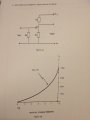
I have to work out the transconductance for the drain current of 2mA.

For the circuit I have Vgs = -1.4V, Vs = 1.4V, Rs = 700 ohms, Voltage drop across Rd = 7.6V and Rd = 3800 ohms

How do I got about working out the transconductance, because I know the equation is obviously gm = ΔId / ΔVgs, but how do I find out the change in Id and the change in Vgs?
 

Attachments

Thread Starter

nothing909

Joined Nov 5, 2016
54
What does the graph in your picture tell you?
It tells me the Q-point at the Vds = 3V with Id = 2mA and the Vgs being say 1.4V? that's what it tells me.

I asked on a separate forum about this question and the guy said this:

1) Realize that what you are looking for is the slope of mutual characteristic curve at the bias point (interchangeable with Q-Point). Can you get this slope? If so, you are done.

or

2a) Inject a small signal about your VGS bias point. Say, 1 V peak-to-peak.
2b) This will give you two new points at VGS,bias + 0.5 V and VGS,bias - 0.5 V
2c) From these 2 points on the curve, you can get the corresponding ID values.
2d) You have ΔVGS = 1 V, because that is what you have injected.
2e) And you also have ΔID from what you did in 2c.

so, would the answer to the question I've been asking be:

doing step 2 if I apply that to the graph that I'm using, the change in Id would be say 0.7mA with the Vgs being 1V so the answer would be 0.7m mho?
 

crutschow

Joined Mar 14, 2008
34,460
...............
doing step 2 if I apply that to the graph that I'm using, the change in Id would be say 0.7mA with the Vgs being 1V so the answer would be 0.7m mho?
Since the plot is not a straight line, that means the transconductance varies with the bias (drain) current.

So you pick the bias current you want for the measurement (in this case 2mA) and then vary Vgs just a small amount around that point (say ±100mV) and measure the change is bias current.
The transconductance (at that point) is then ΔId/ΔVgs.
Make sense?
 

Thread Starter

nothing909

Joined Nov 5, 2016
54
Since the plot is not a straight line, that means the transconductance varies with the bias (drain) current.

So you pick the bias current you want for the measurement (in this case 2mA) and then vary Vgs just a small amount around that point (say ±100mV) and measure the change is bias current.
The transconductance (at that point) is then ΔId/ΔVgs.
Make sense?
upload_2017-3-26_19-21-40.png

so is this right:

if I vary the Vgs 1V, it would make Vgs go to 2.4 from 1.4, which would then make Id = 1.3mA looking at the graph, so the change in Id would be 0.7mA with the change in Vgs being 1V, so the answer using the equation would be 0.7m mho? yes?
 

crutschow

Joined Mar 14, 2008
34,460
if I vary the Vgs 1V, it would make Vgs go to 2.4 from 1.4, which would then make Id = 1.3mA looking at the graph, so the change in Id would be 0.7mA with the change in Vgs being 1V, so the answer using the equation would be 0.7m mho? yes?
Yes, that will give the average transconductance over that region, since it significantly varies over such a large change in current.
That's why a smaller current delta is commonly used for the measurement.
 

Thread Starter

nothing909

Joined Nov 5, 2016
54
Yes, that will give the average transconductance over that region, since it significantly varies over such a large change in current.
That's why a smaller current delta is commonly used for the measurement.
How would I state it when I answer the question would I just say:

Vary Vgs = 1V, so ΔVGS = 1 V,

on graph ΔID = 0.7mA when ΔVGS = 1 V,

mutual conductance = ΔID / ΔVGS = 0.7x10^-3 / 1 = 0.7m mhos

that make sense?
 

crutschow

Joined Mar 14, 2008
34,460
Your originally stated the problem is to find the transconductance at 2mA, but you are finding it about 1.5mA.
So you should measure Vgs at around 2mA, say 1.8mA to 2.2mA and then calculate the transconductance from that.
That would better answer the original question.
 

Thread Starter

nothing909

Joined Nov 5, 2016
54
Your originally stated the problem is to find the transconductance at 2mA, but you are finding it about 1.5mA.
So you should measure Vgs at around 2mA, say 1.8mA to 2.2mA and then calculate the transconductance from that.
That would better answer the original question.
upload_2017-3-26_20-16-27.png

ΔVGS = 0.2 V,

on graph ΔID = 0.2mA when ΔVGS = 0.2 V,

mutual conductance = ΔID / ΔVGS = 0.2mA / 0.2V = 1m mho

is that a good answer?
 

crutschow

Joined Mar 14, 2008
34,460
ΔVGS = 0.2 V,
on graph ΔID = 0.2mA when ΔVGS = 0.2 V,

mutual conductance = ΔID / ΔVGS = 0.2mA / 0.2V = 1m mho

is that a good answer?
Not really.
It looks like the deltas (between red and green lines) are more like 0.45mA and 0.55V to me.
How did you determine your values?
 
Last edited:

MrAl

Joined Jun 17, 2014
11,494
Hi,

Yes when you choose one point above the operating point and one point below (ma) then you must use the total span not just the increment itself. So if you increment by 0.2ma and -0.2ma then the total span is 0.4ma and that is what you use for the division not 0.2ma. You also use the total span for the voltage too being careful to follow the axis scaling given on the graph.
 
Even though one would expect a parabola for the I-V characteristic of a FET, the given problem curve doesn't match your curve for a couple of reasons:

1. The problem curve doesn't have a slope of zero at Vgs = -6V
2. The slope of the problem curve is increasing more rapidly near zero volts than your parabola.

A better fit is this:

Fetx.png

The transconductance at 2 mA appears to be a little less than 1 mS.
 

Bordodynov

Joined May 20, 2015
3,180
Even though one would expect a parabola for the I-V characteristic of a FET, the given problem curve doesn't match your curve for a couple of reasons:

1. The problem curve doesn't have a slope of zero at Vgs = -6V
2. The slope of the problem curve is increasing more rapidly near zero volts than your parabola.

A better fit is this:

View attachment 123519

The transconductance at 2 mA appears to be a little less than 1 mS.
Unfortunately, the curve is a parabola if the working point does not go into a steep area. Look at the post #12.
The exponent is approximately 2.6, not 2. The transconductance of the transistor depends not only on the current, but also on the voltage.
 
Unfortunately, the curve is a parabola if the working point does not go into a steep area. Look at the post #12.
The exponent is approximately 2.6, not 2. The transconductance of the transistor depends not only on the current, but also on the voltage.
The voltage Vds is specified as 3V on the problem curve, but regardless, the given curve is what nothing909 must use to find gm.

My response is directed to post #12. The curve you gave in post #12 does not fit the problem curve well. The slope of the given curve is not zero at Vgs = -6 and your curve's slope does not fit there. Also for example, the problem curve at -3V shows a current of about 1 mA, but your curve shows .6 mA, and at -4V the problem shows about .6 mA but your curve shows about .16 mA. Since your curve is too low at the left side of the plot, you must have a higher slope at the right side to make up for it. This leads to a slope that is too large at 2 mA.
 
Sloping region (a pentode) has a boundary voltage Vdg>|Vto| or Vds=Vdg+Vgs>|Vto|-|Vgs|=6-1.4=4.6>3V
The curve nothing909 is given does not fit well with an exponent of 2 or of 2.6, but it is the curve he must use to get gm. So even though one would expect theoretically that a FET should fit a parabola, in this problem the given curve doesn't do so.

To get an analytical expression for the given curve, something other than a power curve is better, and if a good fit can be obtained, then gm can be derived from the derivative of the fitted expression.
 
Top