JFET common source amplifire @ PSpice (simulation problem)

Thread Starter

michgkou

Joined Oct 3, 2019
43
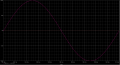
Hi, In this excersise (pic) I have to simulate Vin and Vout of an JFET common source amplifier in PSpice, but running the simulation I receive results not that I expected for (pic)


any idea why this happens ?
 

Attachments

ericgibbs

Joined Jan 29, 2010
18,766
hi mich,
Check this Vgs for a 10mV signal.
E

Update:
Reduce the 1meg down to say 100k and place the 1meg from Vcc to the Gate, bias the FET On.

Check bias voltage and adjust the 100k value to suit the required Drain voltage.


EG 1341.gif
 
Last edited:

ericgibbs

Joined Jan 29, 2010
18,766
hi, @Ian0
Nowhere on my post do I say MOSFET, it says FET.

Your sim shows only a Gain of about 4.5, I hardly call that a working solution.

E
 
Last edited:

Audioguru again

Joined Oct 21, 2019
6,673
When you connect the scope to the capacitor-coupled load then it does not show if the Jfet is saturated or cutoff which is shown by the drain and source voltages.
Since you are doing a simulation that probably uses a BF245 Jfet that has "typical" specs then you do not care if it has A specs or C specs.
 

Ian0

Joined Aug 7, 2020
9,671
hi, @Ian0
Nowhere on my post do I say MOSFET, it says FET.

Your sim shows only a Gain of about 4.5, I hardly call that a working solution.

E
Happy New Year to you.
You were biassing it like it was a MOSFET!
The maximum voltage gain would be Gfs.Rload.
Rload is 1.5k, Gfs is between 3mS and 6.5mS, which gives a voltage gain of about 7 taking an average value for Gfs.
 

Audioguru again

Joined Oct 21, 2019
6,673
When you connect the scope to the capacitor-coupled load then it does not show if the Jfet is saturated or cutoff which is shown by the drain and source voltages.
 

Thread Starter

michgkou

Joined Oct 3, 2019
43
hi mich,
Check this Vgs for a 10mV signal.
E

Update:
Reduce the 1meg down to say 100k and place the 1meg from Vcc to the Gate, bias the FET On.

Check bias volatge and adjust the 100k value to suit the required Drain voltage.


View attachment 256594
Thanks for your answer, I did not note that the excersise says to do a parametric analysis to find VAMPL (I chose 10m just to extract a result). So only this parameter I can change.
 

Thread Starter

michgkou

Joined Oct 3, 2019
43
FINALY.

I had to create at notepad a file with type .mod and write on them the following

.model BF245 NJF(Beta=550u Rs=1 Rd=1 Betatce=-.5 Lambda=10m Vto=-3.44

+ Vtotc=0 Cgd=5p M=.3333 Pb=1 Fc=.5 Cgs=5p Isr=1p Nr=2 Is=100f

+ N=1 Xti=3 Alpha=10u Vk=100 Kf=1E-18 Af=1)

After on Model editor include this file, save them and export to capture part library

Then on OrCAD Capture CIS Lite: Place ->Parts add to library (the .lib file that I export)

And on simulation settings -> Configuration Files -> Library -> import the .lib file and click Add to design

Thats all

The simulation works nicely.

2.PNG
 
Top