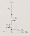
Look at Q1. It is wired as Vgs = 0 +/- signal voltage. Therefore it runs at its normal idle current, give or take.
If Q2 naturally has less idle current than Q1, it will shut off before the signal gets to its least positive excursion.
Too simplistic? You are allowed to ask again.
Another way to look at it: The source terminal of Q2 must be more positive than ground because Q1 can not be transparent to current. There simply must be some voltage across Q1. Therefore, Q2 is biased with its gate being less positive than its source. Q2 is already in a suppressed current flow compared to Vgs = 0 with no signal input. For that reason alone, Q2 must naturally carry more idle current than Q1 at Vgs =0 just to supply Q1 with it's normal Vgs=0 current. Otherwise, Q1 would be at a minimal voltage from drain to source and would not respond to positive excursions on its gate. Q1 would be starved for current and unable to have less voltage on its drain when the gate goes more positive.
Both gates and one source are locked at zero volts. The only voltage that can possibly change is Vds of Q1. If Q1 is already collapsed from drain to source, its drain voltage has nowhere to go.
Brain pain? Yeah. I'm good at this and this circuit is a stretch for me because I have to visualize two apparently identical j-fets which must not be identical if the circuit is to work properly.
 Facebook
 Google
 GitHub
 Linkedin
 65.3 KB Views: 30


