Facebook
 Google
 GitHub
 Linkedin
Hi!
I have made a JDM programmer and now trying to test it according to:
http://reprap.org/bin/view/Main/StripboardJDM#Testing
The circuit seems to be O.K. on first test ( it shows 4.20V) but, then I tick the enable data out the data in does'n get ticked and I get 0.01V between pin 5 and 13, don't know what to do. Please help I have spend money on this and 16F628 and will be my first MCU so, this has to work!!
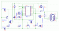
The JDM schematic I used is attached, the clock LED blink when I turn on my PC.
I have made a JDM programmer and now trying to test it according to:
http://reprap.org/bin/view/Main/StripboardJDM#Testing
The circuit seems to be O.K. on first test ( it shows 4.20V) but, then I tick the enable data out the data in does'n get ticked and I get 0.01V between pin 5 and 13, don't know what to do. Please help I have spend money on this and 16F628 and will be my first MCU so, this has to work!!
The JDM schematic I used is attached, the clock LED blink when I turn on my PC.
Attachments
-
 14 KB Views: 20