Issue with step up powe supply MC34063ADR

Thread Starter

kramzar

Joined Mar 7, 2022
35
Hi,

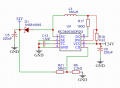
I am trying to design a pcb powe supply that convers 24V DC to 34V dc (for Mbus communication)

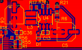
I have designed the folowing power supply as shown in the picture.

When i turn it on it just starts heating up pulling 0.5A under no load (likely shorting or something). I have thecked the pins for any short circuits but everything on the pcb seems fine.

When i remove the 0.22 R19 resistor it works strangely and only generating 6.4V.

Am i mising something from the design? What could be the cause for the shorting?
I have slightly larger coil and capacitor because the exact datasheet parts were not available.
 

Attachments

ronsimpson

Joined Oct 7, 2019
2,989
When i remove the 0.22 R19 resistor it works strangely and only generating 6.4V.
Remove = open or 0 ohms???
0 ohms: the output voltage should be 23 volts or more.
open: the output should be very low.

What is the part number for 180uH inductor. It seems very small.
 

Thread Starter

kramzar

Joined Mar 7, 2022
35
Remove = open or 0 ohms???
0 ohms: the output voltage should be 23 volts or more.
open: the output should be very low.

What is the part number for 180uH inductor. It seems very small.

Remove as in remove the component = open
The output is then a pretty stable 6.4V. not quite sure why.

But when it is present i have a good clue why the chip gets fried.
Since coil resistence + 0.22ohm + shotky diode is very low resistence it prety much shorts the output to the input. But thats how the datasheet tells it so i dont really understand

coil: https://lcsc.com/product-detail/Power-Inductors_3L-COILS-SMTDR32-181M_C326205.html
The datasheet only demands 170uH so it should be fine right?
 

Thread Starter

kramzar

Joined Mar 7, 2022
35
Can you show your design calculations... what frequency were you expecting to run at?
I dont quite understand the question sorry. The chip is a DCDC voltage converter so there is no frequency. unless you mean the switching frequency, which i dont think i can set manualy.

The only calculation i did was for Vout, which is Vout=1.25*(1 + R21/R6)
Hence the 2.2k and 56k values.
I am very novice when it comes to switching power suplies.
 

ronsimpson

Joined Oct 7, 2019
2,989
I am a little surprised it should start up with no load. Even with a saturating inductor.

Open up the 180 ohm resistor. Now the power transistor cannot turn on. The "34V" should measure 22 volts. The IC should not be hot. (no load!)

Under load, what is the load on the 34V?
 

Thread Starter

kramzar

Joined Mar 7, 2022
35
I am a little surprised it should start up with no load. Even with a saturating inductor.

Open up the 180 ohm resistor. Now the power transistor cannot turn on. The "34V" should measure 22 volts. The IC should not be hot. (no load!)

Under load, what is the load on the 34V?
So you reccomend that i increse the inductor to something like 250uH and remove the 180ohm?

The load is a very aproximate 100mA. I have not tested it under full load since i want it to have a stable voltage first. Does it need a base load to function?
 

DickCappels

Joined Aug 21, 2008
10,152
You are going to need an inductor rated at much higher current. The peak current in your circuit will be somewhere in the neighborhood of 1 amp while running, ronsimpson pointed out that your inductor may need to handle more current. iI suggest reducing the value of the timing capacitor to 910 pf or 1000pf.

Without a load the regulator can get "hung up" and not turn on for long periods of time while the output capacitor discharges.

A Schottky diode is recommended for this circuit.

Check out this handy MC34063 calculator(there are several on the internet): https://www.gmsystems.com/switching-reg-calculator-for-mc-34063-or-mc33063.html.
 

Irving

Joined Jan 30, 2016
3,845
OK, you've just pulled the component values from the reference design in the data sheet. I'm not surprised its burning up!

Lets start with the basics.

Vin = 20 - 29v for a nominal 24v lead-acid battery; Vout = 34v +/- 0.25v, 100mVp-p ripple.
The chip is good for 1.5A peak input, so output current = 20/34 *1.5 @85% = 750mA max - IS THAT ENOUGH? if not you'll need to use external switching element. - just seen you want 100mA so OK, design for 150mA.

Oscillation frequency = 50kHz. Higher = smaller inductor. Chip maximum is 100kHz.

Here's the design procedure from the datasheet.
1664467193687.png
EDITE
ton/toff(max) = (34+0.5-20)/(20-1) = 0.763, ton/toff(min)=(34+.5-28)/(28-1) = 0.24
Freq = 50kHz, so ton+toff = 20uS.
toff(min) = 20u/(0.763+1) = 11.3uS, toff(max) = 20u/(1.24)=16.1
ton(max) = 20uS - 11.3uS = 8.7uS, ton(min)= 20uS-16.1uS = 3.9uS
CT = 4e-5 x 8.7uS = 348pF (use 330pF poly film)
Ipk =2 x 150mA x (0.763+1) = 0.53A
Rsc = 0.3/0.53 = 0.566 (use 0.51 1%)
L(min) = (20-1)/0.53 x 8.7u = 311uH (@10% tolerance use 390uH, eg SMTDR107-391K 390uH 0.85A, or Bourns SRR1260-391K
Cout = 9 x 0.15 x 8.7/0.1=117uF (use 150uF)
Vout = 34, R1=1.8k => R2 = 47k
NOTE: EDITED TO CORRECT CALCULATION ERROR
 
Last edited:

Papabravo

Joined Feb 24, 2006
21,159
So it seems that you do have explicit control of the switching frequency, but you seem to have blown right by that particular feature of the part. The object lesson here is that datasheets are NOT tutorials and trying to copy and adapt a reference design from them is fraught difficulties. Try to avoid this temptation in the future.
 

DickCappels

Joined Aug 21, 2008
10,152
I've used many of this type of regulator over the years, and the MC34063 and alternate sources are about a close to fool-proof as can be. The datasheet examples are good starting points but agreed, it is best to go through the calculations or use one of the many online calculators for this part, otherwise one could end up in trouble.
 

Thread Starter

kramzar

Joined Mar 7, 2022
35
OK, you've just pulled the component values from the reference design in the data sheet. I'm not surprised its burning up!

Lets start with the basics.

Vin = 20 - 29v for a nominal 24v lead-acid battery; Vout = 34v +/- 0.25v, 100mVp-p ripple.
The chip is good for 1.5A peak input, so output current = 20/34 *1.5 @85% = 750mA max - IS THAT ENOUGH? if not you'll need to use external switching element. - just seen you want 100mA so OK, design for 150mA.

Oscillation frequency = 50kHz. Higher = smaller inductor. Chip maximum is 100kHz.

Here's the design procedure from the datasheet.
View attachment 277320
ton/toff(max) = (34+0.5-20)/(20-1) = 0.763, ton/toff(min)=(34+.5-28)/(28-1) = 0.24
Freq = 50kHz, so ton+toff = 20uS.
toff(min) = 20u/(0.763+1) = 11.3uS, toff(max) = 20u/(1.24)=16.1
ton(max) = 20uS - 11.3uS = 9.7uS, ton(min)= 20uS-16.1uS = 3.9uS
CT = 4e-5 x 9.7uS = 388pF (use 390pF poly film)
Ipk =2 x 150mA x (0.763+1) = 0.53A
Rsc = 0.3/0.53 = 0.566 (use 0.51 1%)
L(min) = (20-1)/0.35 x 9.7u = 347uH (@10% tolerance use 390uH, eg SMTDR107-391K 390uH 0.85A, or Bourns SRR1260-391K
Cout = 9 x 0.15 x 9.7/0.1=130uF (use 150uF)
Vout = 34, R1=1.8k => R2 = 47k
wow, thank you for this incredible resource and doin all these calculations for me! I will get to testing as soon as possible.
 

Irving

Joined Jan 30, 2016
3,845
wow, thank you for this incredible resource and doin all these calculations for me! I will get to testing as soon as possible.
You're welcome, but note I've edited the values to correct a calculation error - only affects capacitor value.

Next time read & understand the datasheet - also look for the "application notes" document as well.. you may need to look publications from more than 1 manufacturer.
 

ronsimpson

Joined Oct 7, 2019
2,989
Irving shows a peak current of 0.5A, when operating. In this mode you need a 500mA inductor. BUT At startup the current is more like 1.5A with the .22 resistor. Increasing the current limit resistor will help He is limiting the current to 0.76A. Bottom line is you need an inductor that can withstand more current.
1664543700887.png
 

Irving

Joined Jan 30, 2016
3,845
Irving shows a peak current of 0.5A, when operating. In this mode you need a 500mA inductor. BUT At startup the current is more like 1.5A with the .22 resistor. Increasing the current limit resistor will help He is limiting the current to 0.76A. Bottom line is you need an inductor that can withstand more current.
Hi Ron, not sure where you got 0.76A as a current limit from, but I agree his existing inductor is too small an inductance and too puny for the current. The issue I have with your inductor selection is that the inductor you suggest is a ±20% tolerance and at 330uH there is a high chance that the minimum inductance will be significantly below the 311uH minimum required by the design. That's why I spec'd the 390uH parts to be safe.
 

ronsimpson

Joined Oct 7, 2019
2,989
For those following along, the MC34063 is older than many people. lol
There are little PWM on the market that run 10x faster.
The inductor needs to handle the max current. The inductance can be 1/10. Capacitors can be smaller.
Here is an example of a family of more modern parts.
1664561697965.png
1664561918462.png
 
Top