Isolation Transformer Question for Signal Tracing with Oscilloscope

dl324

Joined Mar 30, 2015
18,506
So it seems some people float the device under test where others say "don't float the device under test."
Devices that have earth ground have it for a reason. I have rarely chosen to defeat that protection.

If you intend to connect the scope probes ground to chassis ground (and assuming circuit ground is connected to the chasis), what is it that you think you're gaining by floating the DUT?
 

ronsimpson

Joined Oct 7, 2019
4,878
what is it that you think you're gaining by floating the DUT?
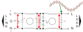
Am I the only person that designs power line filters in power supplies?
I need to see the voltage across C3. The top side has 120/240V 50/60hz and 30V of high frequency trash. The bottom side has anywhere from 3v to 240V of 60hz and very different looking trash. Yes, I know I can purchase a diff probe but several I have only go to 30V. It is hard to find a 400V diff probe. Yes, I can use two probes and subtract them. I find this is not accurate at high frequencies. It can be done. Yes, I have a battery scope designed for working on power lines, but the back light went out. It is only 50Mhz.
I also need to look at the noise across C2 and C1.
We also need to look for, maybe 1khz oscillation, inside the filter because the damping is wrong.
1794269766628.png
Sometimes I have ICs sitting on (load_N) which is not at ground.
People that live on the power line float the scope or the DUT.
 
WOW!! An interesting discussion here!!
ALL ABOUT "Ground" !!
Understand that an isolation transformer is intended to PROVIDE ISOLATION BETWEEN THE MAINS connections AND the transformer's OUTPUT!!
The intention is for there to not be any voltage between either output terminal of the ISOLATION TRANSFORMER and "ground", or the mains NEUTRAL.
So the scope common connection should connect to the COMMON side of the circuit being evaluated ONLY AFTER the isolation transformer.

I see that there is an issue as to the actual meanings of "Ground" versus "Neutral" and "common".

THAT is a topic subject to a whole lot of confusion among many folks who do not understand the difference. Presently I don't have the time to explain it in terms that the unknowing can handle, nor the desire to argue with those who see no difference.
 
Last edited:

Thread Starter

Jsprite7660

Joined Jan 9, 2024
75
If it wasn't already interesting (or probably extremely boring to you all). Here's another curiosity I came across.

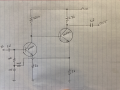
I was practicing the method of ensuring safe ground connection by using a multimeter. Checking that there's no voltage between the scope's alligator ground clip and the circuit's ground point, where I'm going to connect. The circuit is powered by a 9Vdc power adapter. (Photo of circuit attached)

When measuring DC, between the scope's ground clip and the ground point of the circuit, I see zero volts. So I know it's safe.

But when measuring in AC I see 34 Volts between the two points. Why is that?
 

Attachments

That 34 V AC with 0 V DC is a classic high-impedance reading — a 10 MΩ meter will pick up capacitive leakage through the isolation transformer and Y-caps, even though almost no current can flow. Try the same measurement with a 100 kΩ resistor across the meter leads, or switch the meter to its low-impedance mode if it has one; if the voltage collapses to a volt or two, it was stray coupling, not a real fault. Either way, don't clip the scope ground on until you've done that check, and use a proper differential probe for any live mains-side measurement.
 

MrChips

Joined Oct 2, 2009
35,284
If it wasn't already interesting (or probably extremely boring to you all). Here's another curiosity I came across.

I was practicing the method of ensuring safe ground connection by using a multimeter. Checking that there's no voltage between the scope's alligator ground clip and the circuit's ground point, where I'm going to connect. The circuit is powered by a 9Vdc power adapter. (Photo of circuit attached)

When measuring DC, between the scope's ground clip and the ground point of the circuit, I see zero volts. So I know it's safe.

But when measuring in AC I see 34 Volts between the two points. Why is that?
Reading 0 volts on a meter can be the result of many different things, including a non-functioning meter.
Don't rely on this to give you any meaningful information.
 

Thread Starter

Jsprite7660

Joined Jan 9, 2024
75
That 34 V AC with 0 V DC is a classic high-impedance reading — a 10 MΩ meter will pick up capacitive leakage through the isolation transformer and Y-caps, even though almost no current can flow. Try the same measurement with a 100 kΩ resistor across the meter leads, or switch the meter to its low-impedance mode if it has one; if the voltage collapses to a volt or two, it was stray coupling, not a real fault. Either way, don't clip the scope ground on until you've done that check, and use a proper differential probe for any live mains-side measurement.
Ok thank you for that, will do. And sounds good, I'm not doing any live mains side measurements now.
 

kiroma

Joined Apr 30, 2014
309
I assumed the OP wanted to probe willy-nilly with up to two scope probes. Since they have a common ground (whether it's floating or not), that could short things from the scope grounds.
This reopens one of my questions I've had for years: why do it's needed to reference the scope to the mains? Why don't just leave it open?
 

MrChips

Joined Oct 2, 2009
35,284
This reopens one of my questions I've had for years: why do it's needed to reference the scope to the mains? Why don't just leave it open?
I am not sure what you mean by "just leave it open".

Any voltage measuring instrument, voltmeter, or oscilloscope, has to take a voltage measurement between two points, A and B. Line powered oscilloscopes are usually referenced to earth ground, which we can call B as a point of reference. You cannot connect the grounding clip of the oscilloscope to any random point on the DUT (device under test). In other words, point B must be confirmed to be directly connected to earth ground. Connecting the ground clip to the wrong node can cause serious damage to the oscilloscope and/or DUT.

When there is a need to view the differential voltage/signal between two points on the DUT, I prefer to use an isolated (floating) oscilloscope. In such a situation, I use a battery powered handheld oscilloscope.
 

dl324

Joined Mar 30, 2015
18,506
This reopens one of my questions I've had for years: why do it's needed to reference the scope to the mains?
The National Electric Code requires that most equipment with a metal chassis have it connected to earth ground. It's a proven, low-cost method to prevent lethal shocks.

A secondary reason is that it provides a convenient ground reference.

In electrical wiring for houses in the US, neutral is bonded to earth ground at the electrical panel (and only there).
 
Top