 Facebook
 Google
 GitHub
 Linkedin
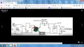
The schematic , capacitor 70 circuit from 2008, according to past references, seems to allow passage of power supply 6A DC current to pass through spark plug when 24kv ignition fires. The toroid transformer of the circuit works ok on high v. side. Others have reported this circuit as working. I am wondering now, exactly how the route is for the 24kv through the output end of the 18vDC power supply that has bridge rectifier 1kv diodes of 4, AC non polarized polypropylene capacitor used as filter, with optional safety spark gap 75v + protective varistor. This design circuit is to NOT USE a protective 30 diodes string bank that loses 21v voltage drop and causes higher input battery draw to power supply Inverter to DC, to overcome the loss because of having a needed increased secondary voltage. I also have insulated high v cable on both ferrite toroid ring transformers to prevent spark over. There is to be an ISOLATED INVERTER TO DC source that is not affected by the incoming high voltage pulses, but allows the passage of 24kv back up to fire spark plug. Diodes and capacitors generally fail due to heat. There is no heat with a high voltage line. (Maybe the end capacitor could be rated as AC 30kv as high quality polypropylene and NOT used as a proper filter capacitor. Would the millisecond's hi v pulse pass through?
Suggestions needed to help me understand the flow path on power supply side.
Suggestions needed to help me understand the flow path on power supply side.
Attachments
-
 169.8 KB Views: 11
Last edited:


