 Facebook
 Google
 GitHub
 Linkedin
Hello,
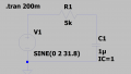
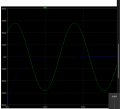
I have been given a cicuit which I modeled in LTspice. The assignment is to modify the simulation deck so that the currents passing through an R2 and R3 show the natural and forced responses' graphs seperately. I have tried this by dividing it into two circuits: One with the sinusoidal voltage source and C1's C set as 0 and the other with only the capacitor with the initial voltage set as 1V. However, the initial currents magnitudes are not right and the forced response model still has a transient face at the start. What am I missing? The graph that I am supposed to arrive at is also attached.

I have been given a cicuit which I modeled in LTspice. The assignment is to modify the simulation deck so that the currents passing through an R2 and R3 show the natural and forced responses' graphs seperately. I have tried this by dividing it into two circuits: One with the sinusoidal voltage source and C1's C set as 0 and the other with only the capacitor with the initial voltage set as 1V. However, the initial currents magnitudes are not right and the forced response model still has a transient face at the start. What am I missing? The graph that I am supposed to arrive at is also attached.
Attachments
-
 42.4 KB Views: 18
 -
 67.7 KB Views: 17

")


