Is there a simple way to reduce the amplitude of this square wave generator?

Thread Starter

zirconx

Joined Mar 10, 2010
171
Hi, I'm working on a raspberry pi water flow meter using this sensor. It uses hall effect sensor to send pulses indicating how much water is flowing.

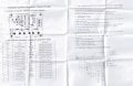
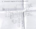
I plan to test my pi software (I'm planning on using this library) using an XR2006 based signal generator like this one (I have the kit, but haven't assembled it yet). That should approximate the signals coming from the water sensor, right?

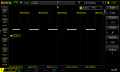
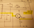
However I notice that the square wave amplitude is not adjustable, and is around 8v. Is there something I can do to reduce it to 3.3v so I can use it with the pi? What about running it through a series of diodes to drop the voltage? Or, I have a bunch of Zener diodes, if I find a 3.3v one, would that work? I do have an occilcope so could measure the output before hooking it up to the pi.

Thanks.
 

Papabravo

Joined Feb 24, 2006
21,095
As long as the load impedance does not change this should be an acceptable solution. A better general purpose solution is to use and amplifier with a gain adjustment and a low output impedance.
 

dl324

Joined Mar 30, 2015
16,788
The square wave output comes directly from the XR2206 and has a DC offset. All of the inexpensive kits seem to have a counterfeit XR2206. I think mine cost $2 or $3 which is about a third of what a genuine XR2206 costs.
clipimage.jpg
 

ronsimpson

Joined Oct 7, 2019
2,954
The square wave output comes directly from the XR2206
We don't know enough. dl324 shows a 10k resistor pulling up but some kits have a buffer on this pin and some have a resistor pulling to another voltage.
If the 10k was a 1k going to 3.3V your problems would be solved.
Or if you removed the 10k and added a 1k to 10k pull up on the Pi board ......
(ok what is the supply say 12V) Then add a 3k from square wave out to ground and you will have near the right output.
 

Thread Starter

zirconx

Joined Mar 10, 2010
171
So I think R2 pulls the square wave high, while pin 11 pulls it down. This creates the square wave? So if I do something different with R2, like add a zener or replace it with a voltage divider, I can modify the device to output a lower voltage square wave?
 

dl324

Joined Mar 30, 2015
16,788
The square wave output is open collector. Putting a resistor from pin 11 to ground should work:
clipimage.jpg
The Exar schematic is one of the sorriest I've seen for a commercial product.
 

Thread Starter

zirconx

Joined Mar 10, 2010
171
You are right, a 510ohm resistor between the square wave output and ground reduces the voltage to just over 3v (with a 9v input to the signal generator). The bottom part of the square wave is still 680mv (with or without the resistor). I think the transition from 3.1v to 680mv is enough for the Raspberry Pi to detect a LOW signal.
 

Attachments

sparky 1

Joined Nov 3, 2018
756
The output is buffered to lower the impedance then with low impedance the use of a variable voltage divider. CQ Jul 75 p71
With TTL resistors would set fixed amplitude level, and was done after the impedance issue resolved in most cases.
Following the buffer the Resistor arrangement can improve an adjustable attenuator and using op amps is a plus.
(one approach used the high impedance input of jfet op amp but was not spectacular)
Using an appropriate type op amp can reduce noise and user set amplitude of small square wave signals.

This same unity gain approach used XR2006, ICL8038, MAX038 ect. Most of the function generators that used these chips,
the TTL level output was available by separate BNC and polar supply used. Some of the instability issues of the low cost function generators solved
by modifying so you can switch between all three waveforms and adjust amplitude.
IMG_20201221_144512.jpg
 
Last edited:

Thread Starter

zirconx

Joined Mar 10, 2010
171
Ok so I think this Q2 transistor on pin 11 is what is meant by "buffered output"? Can someone help me understand what this accomplishes? Pin 11 already outputs a square wave signal, what do we gain by sending it through a transistor?

Is that a 20k pot on the square wave output? Usually a pot has 3 connections. Here we are just using it as a simple variable resistor?

Separate question, I have LM386 and TDA7052A amplifier ICs, could I run the output through one of these to give me more control of the signal?

Thanks.
 

Attachments

Last edited:
Top