Is my relay board design OK?

Thread Starter

Paul_Alexa

Joined Jul 16, 2022
28
Hello,

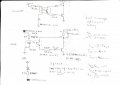
I have reverse engineered a chinese relay module that is used with Arduinos and ESPs. I want to improve it and make it more reliable by using a better relay and adding some isolation slots for the relay. I have the following questions:

I have read that these modules are by design active LOW in order to prevent the accidental turn on of the device controlled by the relay during the development board's turn on phase. I will use it with the ESP32 and I am familiar with its turn on behaviour. Is it better though to leave it to be active LOW? The logic voltage will be 3.3 V but the board will be powered by a 5V source and so will the relay module.

I am wondering if I should use a higher resistance value for the transistor. The relay that I want to drive has a coil with a resistance of 70 ohms.
Is my choice of components appropriate? I will attach a picture below. Thank you.
 

Attachments

Hymie

Joined Mar 30, 2018
1,347
Your Rin resistor at 420 ohm might need to be reduced, after driving the IC diode (volt drop) there may be insufficient current (ideally at least 5mA) to switch the opto transistor on.

With a relay coil of 70 ohm, the transistor base resistor value of 833 ohm could be increased and still work.

The collector of the opto transistor should be connected to the 5V (Vcc) and not the low side of the relay.

I don’t think the circuit will work as is.
 

Hymie

Joined Mar 30, 2018
1,347
With regards the creepage distance across the optos, since both circuits are SELV circuits there is no requirement for safety isolation at these components. But if your relay is switching mains voltages, then there should be a minimum of 5mm between the coil and contact pins (based on 240Vac mains).
 

Thread Starter

Paul_Alexa

Joined Jul 16, 2022
28
Thank you
With regards the creepage distance across the optos, since both circuits are SELV circuits there is no requirement for safety isolation at these components. But if your relay is switching mains voltages, then there should be a minimum of 5mm between the coil and contact pins (based on 240Vac mains).
Thank you for the advice. I will correct it.
 

panic mode

Joined Oct 10, 2011
4,864
what is the purpose of optocoupler in circuit like this? it does not isolate or shift levels or provide triggering irrespective of input signal polarity...
 

Thread Starter

Paul_Alexa

Joined Jul 16, 2022
28
what is the purpose of optocoupler in circuit like this? it does not isolate or shift levels or provide triggering irrespective of input signal polarity...
Hi, I have since corrected my design and prototyped it on a breadboard. It is working.
My goal is to have a relay board as reliable as possible and safely isolated from anything that might occur on the relay's load side. I know that relays provide galvanic isolation. I want to use these boards with industrial grade equipment(actuators, contactors coil, etc...)

I have also considered using SSRs despite them having a lower load current (2 A for an Omron that I was looking at)
Do you consider the optocoupler a waste in this case?
Thanks.
 

panic mode

Joined Oct 10, 2011
4,864
i do... it serves no purpose in this circuit

besides, you are reinventing the wheel. and that os too many parts for what it does. and all of this is already part of any common driver IC, like ULN2803 which is just $0.12. plus the IC has more channels if needed. just connect GND, Vcc and you are all set. you can choose different IC depending on input voltage levels. and if you need to drive larger loads, you can simply parallel channels.

1728476347298.png
1728476445241.png
 

panic mode

Joined Oct 10, 2011
4,864
I have also considered using SSRs despite them having a lower load current (2 A for an Omron that I was looking at)
you can do whatever your application needs...

btw. most of the outputs in industrial equipment are rated much less than 2A.
typical PLC output is rated 100mA, some go up to 500mA, very few are rated 2A or more.
 
Top