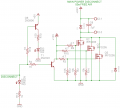
Basically seems right, except you need to limit the current through the collector circuit of the small transistor. Right now a disconnect signal will cause it to blow.
I don't see any function for D4, since the MOSFET body diodes are all in parallel with it.
For the pull up and pull down resistors, maybe someone else has a better idea but I don't really see why you couldn't use a single pull up and especially a single pull down.
Sound good to me. The pulldown resistor is only relevant in the case the transistor fails open, in which case the pulldown does nothing anyway. So eliminate it.
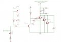
I was debating weather or not to only use one gate resistor until I read the attached PDF. I couldn't fined enough information one way or the other so I decided to be safe than sorry. Same as the diode from the threads I have read here they say you should not rely on the internal diodes. Thanks BSomer for the pic. I have attached the modified circuit. I am assuming this is what bretm was suggesting.
Individual gate resistors are far more important for high frequency usage. I'm assuming your application is almost 0Hz. No harm leaving them in though, and probably an improvement when switching that much current.
I understand not relying on the body diodes, even though you have 3 of them, but why do you need one anyway? Are you concerned about a reverse polarity spike or something like that?
I should actually know better than not giving all the information. I am worried about reverse polarity spikes. This circuit will be the main disconnect for the radio signal if the micro controller senses a bad signal or no signal it will disconnect the power. This circuit will have a 24v 12amp motor and 2 24v 6 amp motors. It will be just a switch on or off no PWM. If I where to use this circuit for PWM how would adding that pull up resistor affect switching time?
I see more and more answers to mosfet questions saying, "don't need an extra diode, there is a diode in the mosfet". When did that change?
From the couple of years ago that I started learning this (thanks to all the answers from AAC) every thing I've read about mosfets is that the diode is "intrinsic"- just a natural occurring result of the manufacturing process. No real value given to it just "magically" appears when a mosfet is made.
Is there new thinking on this mosfet, that I haven't seen/found?

 Facebook
 Google
 GitHub
 Linkedin