Facebook
 Google
 GitHub
 Linkedin
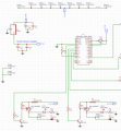
I have designed and simulated an Arduino circuit to sequentially pulse six (6) glow plugs.
I'm using two units to heat glow plugs on a V12 static engine. I need a Neg ground system and I have included flyback diodes to prevent issues with the 12V starter motor inductive load.
The arduino is run in Fast PWM mode and interrupt driven. I have the PWM pulse on pin 3 which runs at 1.409kHz frequency with a 1.40% duty cycle.
Each glow plug is cycled at 1/6th the PWM frequency of Pin 3. The duty cycle is also 1/6th of Pin 3.
The 10K pot will allow me to increase the duty cycle of the signal going to the glow plugs.
My breadboard circuit was not tested long enough to determine the MOSFET was getting hot! It heated the glow plug just fine.
When I received my Printed Circuit Boards (PCB's), I built the 5V supply circuit and one glow plug circuit.
The circuit schematic diagram is missing 4 circuits exactly like the two in the diagram.
I'm powering the PCB with a three cell 2200 mAH 30C LiPo Battery (12.6VDC fully charged).
The Green LED on the Arduino illuminates and the Red LED is being pulsed (LED dimly illuminates).
I do not have the glow plug connected in the circuit and I felt the IRF4905 and it was too warm for me to keep my fingers on it.
A typical glow plug is heated with a 1.5V battery and I measured really close to 4 Amp current draw.
I've searched the forums and there are lots of similar issues, but I don't know enough to solve my problem.
I have a 1.409kHz signal on pin 3 with a 1.40 % duty cycle.
Pin 2 should have a signal 1/6th of the PWM signal on pin 3. I measure 234.2 Hz and duty cycle of .25%.
Transistor 2N2222 has 11.1V on the collector, freq 234.2 and 99% duty cycle.
I think the MOSFET turn on voltage must be low.
Have I chosen the wrong MOSFET? What can I do to lower the MOSFET temperature?
Stuffing the PCB and 6 hot MOSFETS won't work in a PLA 3D printed case.
All comments appreciated.
pdf of schematic
Attachments
-
 45.8 KB Views: 53
 -
47 KB Views: 31
Last edited by a moderator: