IR2110 high side not working

Thread Starter

MSemz

Joined Jan 19, 2021
14
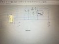
Three months ago I made a circuit to drive small dc motor with only one Mosfet connected as high side and used IR2110 to drive the Mosfet and it worked. Now I’m trying to remake the same circuit and it’s not working. I checked the connections like 100 times also I went back to the simulations I did and still the HW not working.

The HW behavior is connecting HIN pin to either VDD or GND the motor is rotating and the IR2110 is getting really hot in very short time.

I tried to remove the gate from HO and connect it to VS manually the motor stops then reconnect it to VB and the motor starts again. Also I noted when gate is not connected to IR2110 it’s not heating.
I thought maybe it’s damaged and tries three different IR2110 and behaves in the same manner. I checked the low side and it works fine on all 3 of them.

Is there anything I’m missing that could cause this behavior ?
 

Attachments

ronsimpson

Joined Oct 7, 2019
2,986
Do you have a load on the output? "VS" must be pulled hard to ground for C1, C2 to charge up. You can not run at 100% duty cycle.
 

Orson_Cart

Joined Jan 1, 2020
90
The above are correct - the 2110 does not support high side drive without a low side device to charge the boot strap cap - in you last incarnation it was likely there was a load on the source at all times ( including at cold start ) that allowed the boot strap cap to charge and at other times when the top device turned off and the output briefly traversed low at times - always a good idea to read the data sheet carefully to try to gain an understanding of how any IC works .....
 

Thread Starter

MSemz

Joined Jan 19, 2021
14
Do you have a load on the output? "VS" must be pulled hard to ground for C1, C2 to charge up. You can not run at 100% duty cycle.
I have a motor which is connected to ground the motor has resistance 10 ohm so I think it should work fine.

not 100% duty cycle the issue is when connecting HIN to ground the motor rotates
 

ronsimpson

Joined Oct 7, 2019
2,986
I think the motor produced a negative voltage that pulled "VS" below ground and killed the IC. There should be a diode across the load.
1633089179082.png
 

Orson_Cart

Joined Jan 1, 2020
90
If your layout is too open and the grounds are not solidly connected to each other - when the high side turns off the source of the fet can go below gnd due to inductive layout effects - this can easily kill the 2110 - this has been well documented - even by IR in the early days and various remedies are published on the web. No local decoupling is also a typical newbie oversight.
 

Thread Starter

MSemz

Joined Jan 19, 2021
14
If your layout is too open and the grounds are not solidly connected to each other - when the high side turns off the source of the fet can go below gnd due to inductive layout effects - this can easily kill the 2110 - this has been well documented - even by IR in the early days and various remedies are published on the web. No local decoupling is also a typical newbie oversight.
So you also recommend using diode as ronsimpson proposed ?
 

shortbus

Joined Sep 30, 2009
10,045
I have a motor which is connected to ground the motor has resistance 10 ohm so I think it should work fine.
I'd have to disagree with that. The motor has a commutator and as it rotates it is making and breaking ground. And as it goes to speed there may not be enough time to charge the bootstrap capacitor. When the circuit is first started there's a 50/50 chance the the commutator is at a spot that is connected to ground and enough time to charge the boot cap. But as it starts to turn there is less and less charge time .
 
I'd have to disagree with that. The motor has a commutator and as it rotates it is making and breaking ground. And as it goes to speed there may not be enough time to charge the bootstrap capacitor. When the circuit is first started there's a 50/50 chance the the commutator is at a spot that is connected to ground and enough time to charge the boot cap. But as it starts to turn there is less and less charge time .
Also, a motor is not a resistor. If it is turning, it is generating it's own EMF which is raising the low side of the bootstrap charging elements.
 
Can you use a low-side switch? Much easier. That driver isn't going to be able to develop gate voltage (via bootstrapping) unless there is another switch to ground and the duty cycle is less than 100%. That said, you might try reducing the duty cycle to see if you can get away with it.

If you have to switch the high side, either come up with something other than bootstrapping to drive the NMOS gate or consider a PMOS switch.
 

Thread Starter

MSemz

Joined Jan 19, 2021
14
Can you use a low-side switch? Much easier. That driver isn't going to be able to develop gate voltage (via bootstrapping) unless there is another switch to ground and the duty cycle is less than 100%. That said, you might try reducing the duty cycle to see if you can get away with it.

If you have to switch the high side, either come up with something other than bootstrapping to drive the NMOS gate or consider a PMOS switch.
Yes I will do that and switch to low side driving but I need expansion -just to understand- for that.

I connected the HIN to ground -so the motor should not rotate- but what happened is the motor is not rotating for 2 or 3 sec and then it rotates while HIN connected to ground and the IR2110 is getting hot. Is the reason the missing diode around the load which made negative voltage on VS and damaged the IC ?

The IC low side still working fine. So Is it possible to damage just a part of the IR2110 as high side is damaged and low side is working ?
 
Top