IR Transmitter circuit help

Thread Starter

Native34

Joined Mar 30, 2020
17
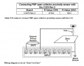
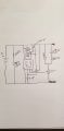
Let me first start out by stating the reason for this circuit. I have built a CNC Vertical Mill. I am now in the process of trying to create a wireless probing system to aid in the setup of machining work offsets. I have a working receiver, that when the machine input pin doesn't see 5v the receiver the machine doesn't think a probing strike has been triggered. So if i take a regular tv remote and constantly press any button the receiver is happy, and when i let go of the button the receiver senses it as a probe hit. I am trying to recreate this with an IR Transmitter circuit. I have the circuit mostly working, as in the transmitter will send a trigger to the receiver, but it is only a short hit. I need for the transmitter to act like the button is constantly pressed on a remote until the trigger is broken, then stay that way until the button is pressed again. Currently the transmitter will just get the receiver to blink and not stay in the on or off state as long as the button is pressed or not pressed. I am attaching a schematic of my current circuit.
 

Attachments

Dodgydave

Joined Jun 22, 2012
11,285
Why don't you use an old tv remote control, and just short one of the buttons out ?

TV remotes use a pulsed coding system , not just on then off..
 

Thread Starter

Native34

Joined Mar 30, 2020
17
I can't use a tv remote, as the circuit needs to fit into a small tool housing that goes into the machine to make the triggers when the probe hits the part. It is designed to give the user an accurate way to set your zero locations for milling a part. From my current circuit can i get the circuit to pulse the IR LED to emulate a button press? in its resting state, then in its hit state it needs to emulate a button release, until the probe is moved off the side of the part, then it sends the button press again. I am attaching a video of what this is used for. The reason for making my own is that the retailers want upwards of $1000- $10,000 for a commercial system. I am only using this for hobby and do not have that kind of money.
 

Dodgydave

Joined Jun 22, 2012
11,285
Ypu can make the 555 pulse using another 555, like this circuit, set Ic2 to 38Khz, and set the Frequency of Ic1 to pulse on and off at the speed you want..


infrared-intrusion-barrier-transmitter.png
 

Thread Starter

Native34

Joined Mar 30, 2020
17
I will give this a try. A couple of questions. What does the arrow mean that points to R4(27K)? and Where do i place a switch to trigger the on and off state of the output?
 

cmartinez

Joined Jan 17, 2007
8,220
The arrow in R4 means that R4 is not a resistor, but a potentiometer. You could place a switch at the power supply to turn the whole circuit on and off, right at where the +5V DC tag is.
 

wayneh

Joined Sep 9, 2010
17,496
What does the arrow mean that points to R4(27K)?
That indicates a variable resistor. It's not required to be variable if you know exactly which resistance you need there. It's common, for instance, to build a prototype with a variable resistor and then, once the resistance is dialed in, replace it with a fixed resistor.
 

iimagine

Joined Dec 20, 2010
511
I kept seeing this type of design almost every where. Why on earth would anyone want to waste current through R1 and
R3 when they could just use the output pin 3 and direct couple to pin 7 to charge the capacitor? More symmetrical waveform and less components.
 

Thread Starter

Native34

Joined Mar 30, 2020
17
Is there an easier way to make a wireless circuit that will accomplish whats in this image? All i'm trying to accomplish is 5v and input pin are tied together, and when they touch a ground the CNC control software sees that the pin was pulled from high to low or low to high, I can never seem to remember which way that is, and then performs a function based off the state change of the pin. Just using a IR LED and an Photodiode would work, The only problem with them is that i can't seem to get the 2-5 feet distance apart that i need.
 

Attachments

Sensacell

Joined Jun 19, 2012
3,432
How much latency (delay) can you tolerate from detection to when the pin changes state?

This is a critical design parameter that must be defined.

The machine is moving as it's looking for the edge? a delay would significantly impact the accuracy?
 

cmartinez

Joined Jan 17, 2007
8,220
This is a critical design parameter that must be defined.
The one and only critical parameter that I think he should be looking at is repeatability. And I honestly don't think a light sensor will deliver what he needs. He should be looking at either a high precision inductive sensor, or possibly one of those ruby contact balls normally used in CMMs.
 

Sensacell

Joined Jun 19, 2012
3,432
The one and only critical parameter that I think he should be looking at is repeatability. And I honestly don't think a light sensor will deliver what he needs. He should be looking at either a high precision inductive sensor, or possibly one of those ruby contact balls normally used in CMMs.

I don't see where the OP describes using the IR light to probe physically, it seems that he wants to use the IR as a data link for a mechanical/electrical probe?
 

Thread Starter

Native34

Joined Mar 30, 2020
17
Correct the IR is only to trigger the receiver which makes the contact to the ground. I think a few milliseconds of latency are fine. repeatability is pretty critical in this application. Most of the very high end companies are using radio frequency to accomplish this, but again those companies are charging very high prices for the probing system. Price is definitely an issue for me and ease of implementation.
 

cmartinez

Joined Jan 17, 2007
8,220
Correct the IR is only to trigger the receiver which makes the contact to the ground. I think a few milliseconds of latency are fine. repeatability is pretty critical in this application. Most of the very high end companies are using radio frequency to accomplish this, but again those companies are charging very high prices for the probing system. Price is definitely an issue for me and ease of implementation.
Ok, let me see if I'm understanding you correctly. You want to set up a device that will trigger a wireless receiver when the tool in your CNC reaches a point to be referenced as a zero. This receiver in turn will activate an input in your machine's CNC controller. Is that right?
 

cmartinez

Joined Jan 17, 2007
8,220
CMartinez, That is correct. The Wireless transmitter will be the probe that is in the cnc machine that triggers the receiver.
And it HAS to be wireless? ... why don't you place a wired probe on one side of your workpiece, and then have the tool travel to that probe so as to set its zero before running a program?
 

Thread Starter

Native34

Joined Mar 30, 2020
17
I had a solution like that, but I kept pulling the wires out. They would either get stuck on something or i would forget and the spindle would spin and pull the wires out. Getting really sick of soldering wires due to wire placement or my forgetfulness.
 

wayneh

Joined Sep 9, 2010
17,496
I had a solution like that, but I kept pulling the wires out. They would either get stuck on something or i would forget and the spindle would spin and pull the wires out. Getting really sick of soldering wires due to wire placement or my forgetfulness.
This problem has been solved, see MagSafe. I know it's not what you're looking for but might be a cost-effective solution that would save a lot of time and trouble designing and building a circuit. You can get the mating parts inexpensively on eBay.
 
Top