IR Sensing circuit using Phototransistors

Thread Starter

Kundan TU

Joined Apr 3, 2015
9
Hi all,

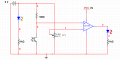
I am making a simple black and white bubble sensing circuit using LM358, IR LED, Phototransistor(L14G1) and potentiometer. I am getting several problems using this phototransistor because of daylight. It is also not reliable smtm it work fine but again it dont.
Previously I used L14G2 and all other resistance values were same and it was working fine. Then I ordered L14G2 but the supplier shipped me L14G1/3 /ST- . Now it is not working as before.

Also, I have to replace the potentiometer with two fixed resistances for further application of this circuit. I am totally stucked here and could not think how to proceed.

Please reply ...
kundan
 

Attachments

MrChips

Joined Oct 2, 2009
30,714
When working with ambient light it would be better to modulate (switch on and off) your LED. This way the AC signal detected by the photosensor is less sensitive to ambient light.
 

MikeML

Joined Oct 2, 2009
5,444
Best way is to modulate the emitter at ~kHz, and then use an AC detection scheme after the phototransistor. Ambient light is DC.

The 5Meg load resistor is way too high. Try 10KΩ to 50KΩ
 
Last edited:

Søren

Joined Sep 2, 2006
472
I am making a simple black and white bubble sensing circuit
First things first...
What kind of bubbles are you trying to detect and what are the specifics on the bubbles?
What is the distance between emitter and detector?
How are they arranged - side by side or opposite each other?
 

Thread Starter

Kundan TU

Joined Apr 3, 2015
9
First things first...
What kind of bubbles are you trying to detect and what are the specifics on the bubbles?
What is the distance between emitter and detector?
How are they arranged - side by side or opposite each other?
These bubbles are on a paper. They are arranged side by side.
 

Søren

Joined Sep 2, 2006
472
These bubbles are on a paper. They are arranged side by side.
That answer gave me just about nothing to work with.
My 4 questions were
What kind of bubbles are you trying to detect and what are the specifics on the bubbles?
What is the distance between emitter and detector?
How are they arranged - side by side or opposite each other?

Each time you see a question mark "?" it means that you need to reply with the answer, or we won't be able to offer much help.
I, for one, does not have the patience to drag these answers out of you - they're solely in your interest to answer.

In case you don't know what I mean with "the specifics of the bubbles", I'm referring to material, color, opaqueness, size, distance to neighboring bubble and so forth. The remaining questions should be easy, but do ask if you're puzzled by any of them - just ignoring them will only result in you being ignored, as solutions needs details to operate on.
But hey, it's Easter holiday, so you get a free retry :D
 

Thread Starter

Kundan TU

Joined Apr 3, 2015
9
When working with ambient light it would be better to modulate (switch on and off) your LED. This way the AC signal detected by the photosensor is less sensitive to ambient light.
That answer gave me just about nothing to work with.
My 4 questions were
What kind of bubbles are you trying to detect and what are the specifics on the bubbles?
What is the distance between emitter and detector?
How are they arranged - side by side or opposite each other?

Each time you see a question mark "?" it means that you need to reply with the answer, or we won't be able to offer much help.
I, for one, does not have the patience to drag these answers out of you - they're solely in your interest to answer.

In case you don't know what I mean with "the specifics of the bubbles", I'm referring to material, color, opaqueness, size, distance to neighboring bubble and so forth. The remaining questions should be easy, but do ask if you're puzzled by any of them - just ignoring them will only result in you being ignored, as solutions needs details to operate on.
But hey, it's Easter holiday, so you get a free retry :D
Bubbles are on a paper as in the OMR sheets. The colour of the bubble will be preferably black, bubble is almost eliptical horizontal(major)- 3.9mm & vertical(minor)- 2.1mm , horizontal distance centre to centre with the nearby bubble is 8.5mm, vertical distance with the consecutive one centre to centre is 4mm, Exactly i can't say about the thickness of the paper but it is slightly thicker than 100gsm paper maybe 170-190gsm.
Emitter and detector are arranged side by side and close enough at an appropriate angle. The vertical distance between the pair and the bubble varies with the resistance, angle between them and other factors.

Hope I answered your questions.
Thanks
kundan
 

Søren

Joined Sep 2, 2006
472
Bubbles are on a paper as in the OMR sheets. The colour of the bubble will be preferably black, bubble is almost eliptical horizontal(major)- 3.9mm & vertical(minor)- 2.1mm , horizontal distance centre to centre with the nearby bubble is 8.5mm, vertical distance with the consecutive one centre to centre is 4mm, Exactly i can't say about the thickness of the paper but it is slightly thicker than 100gsm paper maybe 170-190gsm.
Emitter and detector are arranged side by side and close enough at an appropriate angle. The vertical distance between the pair and the bubble varies with the resistance, angle between them and other factors.

Hope I answered your questions.
You most certainly did :)
I don't know OMR sheets and when I hear "bubble" I'm thinking of a 3-dimensional object like eg. a soap bubble. To me a more descriptive word would be circle or dot, but I assume it's a sort of multiple choice paper where people fill out a form.

You could use something like the QRE1113 from Fairchild https://www.fairchildsemi.com/datasheets/QR/QRE1113.pdf
They're extremely good for this kind of work. I've used them on several occasions.

The L14G1 is made for twice the collector current and you were starving the L14G2 already, so all you need is a slight redesign.
First, replace the pot with eg. two 47k resistors (might as well save a little current here and the op-amp doesn't mind) to settle node #1 at half the battery voltage.

I assume you use low current (~7.5mA) in the IR-LED to save current if it's run on a PP3 (9V square battery)?

Change the 5M resistor to a potentiometer of 100k in series with a 10k resistor and measure the voltage of node #4 (when reading a "bubble") while you adjust the potentiometer to get node #4 to at least 3/4 of the battery voltage (a 9V battery is specified as flat at 5.4V) on a dot and check that it gets to max. 1/4 of the battery voltage when not on a dot.

If you can't fulfill both criteria, either use a larger potentiometer, or adjust the current into the IR-LED, depending on which won't behave.
Or, post the voltage range covered (on a dot as well as on white paper) with the potentiometer here and I can tell you how to proceede :)

Just using a lower resistor (for the 5M) should solve it, but with careful selection, you can get it to work until the battery is flat, rather than having to maybe toss it when it reaches 7..8V.

BTW. What voltage range do you see at node #4 as is?


EDIT. I was wrong on the Fairchild number - the reflective sensors that I was talking about can be found here not QRE1113, but QRB1133/1134


Attachments

Last edited:

Thread Starter

Kundan TU

Joined Apr 3, 2015
9
You most certainly did :)
I don't know OMR sheets and when I hear "bubble" I'm thinking of a 3-dimensional object like eg. a soap bubble. To me a more descriptive word would be circle or dot, but I assume it's a sort of multiple choice paper where people fill out a form.

You could use something like the QRE1113 from Fairchild https://www.fairchildsemi.com/datasheets/QR/QRE1113.pdf
They're extremely good for this kind of work. I've used them on several occasions.

The L14G1 is made for twice the collector current and you were starving the L14G2 already, so all you need is a slight redesign.
First, replace the pot with eg. two 47k resistors (might as well save a little current here and the op-amp doesn't mind) to settle node #1 at half the battery voltage.

I assume you use low current (~7.5mA) in the IR-LED to save current if it's run on a PP3 (9V square battery)?

Change the 5M resistor to a potentiometer of 100k in series with a 10k resistor and measure the voltage of node #4 (when reading a "bubble") while you adjust the potentiometer to get node #4 to at least 3/4 of the battery voltage (a 9V battery is specified as flat at 5.4V) on a dot and check that it gets to max. 1/4 of the battery voltage when not on a dot.

If you can't fulfill both criteria, either use a larger potentiometer, or adjust the current into the IR-LED, depending on which won't behave.
Or, post the voltage range covered (on a dot as well as on white paper) with the potentiometer here and I can tell you how to proceede :)

Just using a lower resistor (for the 5M) should solve it, but with careful selection, you can get it to work until the battery is flat, rather than having to maybe toss it when it reaches 7..8V.

BTW. What voltage range do you see at node #4 as is?
A lot of thanks for your valuable suggestions. I will definitely try all these.
at node 4 I am getting 150-200mv while phototransistor is receiving light.
 

MikeML

Joined Oct 2, 2009
5,444
Twice now you have received advice that your basic circuit for producing a detected signal is wrong. Think of the photo-transistor as a current source whose current is a function of the IR flux arriving at the photo-transistor. Look at this plot taken right off the data sheet:
Il.gif

To get the maximum sensitivity to illumination changes, the Vce across the photo-transistor needs to be set between 1V and 10V. Tthe resistor between node 4 and node 5 (now 5MegΩ) needs to be changed to do that. It should be selected so that with the normal illumination level (emitter on, proximity to paper), the voltage at node 4 is about 5V.

Then set the trip point for the LM358 used as a comparator to near 5V. The comparator should be modified to include some positive feedback so that it exhibits at least a few mV of hysteresis.
 

Thread Starter

Kundan TU

Joined Apr 3, 2015
9
Twice now you have received advice that your basic circuit for producing a detected signal is wrong. Think of the photo-transistor as a current source whose current is a function of the IR flux arriving at the photo-transistor. Look at this plot taken right off the data sheet:
View attachment 83423

To get the maximum sensitivity to illumination changes, the Vce across the photo-transistor needs to be set between 1V and 10V. Tthe resistor between node 4 and node 5 (now 5MegΩ) needs to be changed to do that. It should be selected so that with the normal illumination level (emitter on, proximity to paper), the voltage at node 4 is about 5V.

Then set the trip point for the LM358 used as a comparator to near 5V. The comparator should be modified to include some positive feedback so that it exhibits at least a few mV of hysteresis.
Thank you Sir, I was also going through this waveform while reading datasheet but could not understand much. I will definitely follow your words.
 

Thread Starter

Kundan TU

Joined Apr 3, 2015
9
And what is the voltage when it's over a dot?
It is showing approximately 1.20V. I am measuring the voltage with DMM, do not know whether the internal resistance of the DMM will hamper the result or not. But I really doubt the result. If u can tell any alternative.

When the Phototransistor will be over the dot then it should be OFF.

Thogh when I check it in Multisim software then while the Phototransistor is ON then it is showing 0V and while it is OFF then it is showing almost 9 V. Ideally it should be like this.
 

Søren

Joined Sep 2, 2006
472
It is showing approximately 1.20V. I am measuring the voltage with DMM, do not know whether the internal resistance of the DMM will hamper the result or not. But I really doubt the result. If u can tell any alternative.
With the 5M in place, the DMM will change the result somewhat, but how much depends on whether the DMM has an input impedance of eg. 1GOhm and 10GOhm.


When the Phototransistor will be over the dot then it should be OFF.

Thogh when I check it in Multisim software then while the Phototransistor is ON then it is showing 0V and while it is OFF then it is showing almost 9 V. Ideally it should be like this.
Yeah well, there's sims and there's reality :D

To be fair to Multisim, it's an electronics sim, not a light sim - how would it know eg. distance, which is a big part in how it goes down. Further, I think you have used a generic phototransistor, rather than the one you use in the circuit.

If you split the trimmer into 2 resistors as I told you, you can use the trimmer as a variable resistor in series with eg. 470 Ohm in place of the 5M that you have now.
Then you should be able to dial in a working setting, carefully remove the trimmer without moving the wiper) and measure its value. Add the 470 Ohm in series with it and you have the new value needed.
 
Top