IR 2101 FET DRIVER problems.. (a Full bridge inverter project)

could it be a problem with the fets ? (NEW)

  • yes

    Votes: 1 20.0%
  • No

    Votes: 4 80.0%

  • Total voters
    5

Thread Starter

Engproject09

Joined May 11, 2009
4
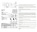
Hey guys attatched is the test schematic from IR and some notes of the problems i am having with the IR2101..

I need some help in getting it to work. I cant even get the test circuit to work.

can someone explain how i need to calculate the proper capacitance and diode values it would be ace too.. But most importantly a proceedure and circuit would be much appreciated. I have another little DC motor that i have been using as the load to test this. I am also sending the pulse to the HIN and LIN from a micro, or function generator.

the IR2101's are intended to be used in a full bridge inverter to cotnrol a BLDC, pulsed from a PIC micro controller.

cheers:
 

Attachments

Thread Starter

Engproject09

Joined May 11, 2009
4
Did you get the data sheet? -

Yeah I have the data sheet, Im just having trouble understanding why its not working.. More specifically what i should be seeing at the VB pin to turn on the top FET. It should be higher that the rail voltage, but im not seeing it.
 

Tahmid

Joined Jul 2, 2008
343
Hi,
The HIN is the input signal for turning on the high-side MOSFET and LIN is the one for the low-side MOSFET. Use larger capacitors than 0.04uf and use the same value capacitance in between vcc and gnd.
The capacitors are there to create an isolated gate drive signal for the high side MOSFET. The driver creates a "virtual ground" using the capacitor thus creating an isolated voltage from gate to source of the high side MOSFET.
For the diodes, use ultrafast types (I use BYV26E).
The circuit given in the datasheet is fine. All you need to do is create an oscillator with symmetrical complementary outputs (eg. 4047, SG3525, 3524, 3526, Tl494, etc) and connect the output signals(Q and Q inverse) to the HIN and LIN pins.
Hope this helps.
Good luck.
 
Thanks very much for your help

I still cant get them working though..

any chance of a simple test circuit just so i can observe the HO and LO outputs!!
cheers
and thanks again
 

Tahmid

Joined Jul 2, 2008
343
Hi,
Here is a test circuit:


Apply power to where is marked 12v and gnd. And connect oscilloscope probes to test point hi and test point lo.
Hope I could help.
 
Thanks very much mate!

Finally i have again setup the circuit provided on the IR2101 data sheet! and with all the capacitors and correct diode the circuit is now stable!
Hence i have connected 36 volts to the rail and power the chip with 12 Vcc. and for once the chip isnt overheating or blowing.

Now i have connected the outputs to a resistor. Hence i am thinking that when i PWM the hin and lin i should be able to see voltage at the resistor right ?

Your said i needed an oscillator... can i just use a Function generator ? or can i trigger the LIN and HIN with just 5 volts from another power suply ? or will this cause problems ? can i just tie the LIN to ground and pulse the HIN ?

whats the best way to observe these fets switching

thankyour so much for your continued help
 
Top