Interleaved PFC boost converter

Thread Starter

Victor07

Joined Apr 16, 2019
21
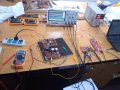
I am designing an interleaved PFC boost converter to convert 220vac to 400vdc, the fuse keeps breaking anytime I apply PWM to the gate of the MOSFET, I have tried reducing the duty cycle of the PWM it still keeps breaking my fuse and damaging my MOSFET.
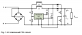
let me attach the circuit.
Thank you
 

Attachments

ronsimpson

Joined Oct 7, 2019
2,985
We need more information. I am certain the picture is not what you made. There are many things we don't know.
What inductors?
What IC?
How is the layout? PCB or bread board?
pictures?
etc.
 

Thread Starter

Victor07

Joined Apr 16, 2019
21
Thanks for the quick response, the schematic is shown, the MOSFET is irf840 and the driver is mcp1403, I was able to get the PWM from the output of the most driver, but at applying the PWM to the gate of the MOSFET it immediately cut my fuse. I have changed the PWM duty cycle and the amplitude the result did not change.
I was able to get good results in stages before applying the PWM the output voltage was about 317vdc at an input of 230vac.
The circuit on the Veroboard is the test circuit, not the permanent circuit.
 

Attachments

ronsimpson

Joined Oct 7, 2019
2,985
In the picture, I do not see L11 & L14. I only see one.
In a PFC there is never a large capacitor after the diodes. C68. This is not causing the fuse to pop.
I see green wire ground. Next, I see a "GND", where dose that connect to? Scope? Computer? "GND" is not ground!! If you connect it to a scope lead you will pop the fuse!
 

Ian0

Joined Aug 7, 2020
9,667
What generates the control signals? What is the operating mode: continuous conduction, critical conduction or discontinuous?
 

Thread Starter

Victor07

Joined Apr 16, 2019
21
The green wire and the red wire close to it are to measure the output voltage via a resistor divider. All the GNDs have been connected together in both the rectification stage and the boost stage, but the GND of the microcontroller is NOT connected to the GND of the boost and rectification stage. I have only the PWM signal connecting to the gate of the MOSFET.

I am testing it gradually is the reason why I am using one inductor and one MOSFET, I have tries the two MOSFET and two instructors as in the schematic but it cut the fuse.

I used a c2000 microcontroller to generate the PWM, with the frequency of 100kHZ, I used mcp1403 as the driver and irf840 MOSFET, the inductor is 1422514c(2.2mH and current rating of 1.4A) the design output power is 400W, the maximum output voltage is 400VDC, it is meant to operate in continuous conduction mode I have not implemented the feedback circuitry yet.

I used the launchpad to generate the PWM, I want to get an output close to expected before implementing the control, the fuse breaks as a result of it not being controlled or because I'm not using the right inductor?
 

ronsimpson

Joined Oct 7, 2019
2,985
You said all the grounds with the red lines are connected together.
I think you said the green wire ground is also connected. ???
There is no ground from micro to the red grounds. ???
1658715565143.png
 

Thread Starter

Victor07

Joined Apr 16, 2019
21
Do you mean all the ground should be connected? But I am using a launchpad to drive the gate, will the high voltage ground not affect or damage my microcontroller/ launchpad if I connect all the ground? or which should be separated and how do I separate them?
 

Ian0

Joined Aug 7, 2020
9,667
Let’s call them 0V, because one thing that they certainly aren’t is ground!
You are connected to the negative of rectified mains, which is a half sinewave signal that varies between 0V and -325V (assuming that neutral is earthed somewhere). You have to bear in mind that all you control circuitry is at this potential.
For prototyping, if you don’t have a double insulated computer with a completely plastic case, that only connects to anything else by Wi-Fi, I’d suggest an isolating transformer! Then you can safely connect rectified-mains negative to earth.
 

ronsimpson

Joined Oct 7, 2019
2,985
Do you mean all the ground should be connected?
I am trying to find out what you did.

Do not connect Green Ground to the other ground. That will brake the fuse.
The computer's ground needs to connected to the gate driver's ground.

I use an isolation transformer, as Ian0 said.
OR
I use a 0-400V dc bench supply to drive the "power line wires". (current limited)
Then I use a 5V or 12V supply to power the computer. Also, current limited and isolated from ground.
 

Thread Starter

Victor07

Joined Apr 16, 2019
21
Thank you to everyone that has contributed it has really helped to improve the result I am getting. I connected all the groud except for the MCU to the earth ground and o changed the transistor to irfp460, with one channel of the interleaved and without control, I am getting about 320 volts.
another issue I am having is that the value of the output voltage (320V) tends to decrease and the PWM as seen on the oscilloscope fluctuates and disappears most time.
 

Thread Starter

Victor07

Joined Apr 16, 2019
21
The output voltage as seen on the multimeter is 270V and 320V in the two pictures I sent.

Like I said before the oscilloscope at 320V did not capture the PWM at this point the MOSFET is been driven, and in the 270V picture, we could see the PWM clearly on the oscilloscope.

As the PWM fluctuates in the oscilloscope the 320 volts tend to decrease to about 270 volts. As seen in the multimeter the 300V is a result of a decrease from 320V, and after a while, it will get to 270V.

With time or after a few seconds I observed that the output voltage decreases to about 270V from 320V.

How can I resolve the issue of the decrease of the output voltage and the PWM disappearing from the oscilloscope?

Thank you.
 

Attachments

Top