Interleaved active clamp flyback converter

Thread Starter

Dipak_rathod

Joined Nov 18, 2019
1
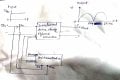
as per the figure we provides a dc voltage as a input to the interleaved active clamp flyback converter block, provide a PWM signal to the MOSFET which is in interleaved block for switching purpose. PWM signal is generated by the microcontroller which has a fix frequency 57 KHz and 50 % duty cycle then we got a output like triangular waveform. actually we will need a output like a given figure so which type of PWM output will be provided to the switching MOSFET, so we got proper output of the interleaved active clamp flyback converter.
 

Attachments

Alec_t

Joined Sep 17, 2013
14,280
Welcome to AAC!
You will need to vary the PWM duty cycle in a half-sinusoid manner such that it follows the desired output waveform. This is usually done using a look-up table.
 

DickCappels

Joined Aug 21, 2008
10,153
...and the appropriate interrupts to read the next table entry and sent it to the PWM module.

Following PWM you will need a reconstruction filter to smooth out the transitions between samples.

As an example, here is a cycle of a sine wave as 96 samples.

;Assumes a bipolar sine wave with a count of 128 being the midpoint
;.db 128,136,144,152,160,168,176,184,191,198,205,211,217,223,228,233,237,241,245,248,250,252,253,254,255,254,253,252,250,248,245,241,237,233,228,223,217,211,205,198,191,184,176,168,160,152,144,136,128,119,111,103,95,87,79,71,64,57,50,44,38,32,27,22,18,14,10,7,5,3,2,1,1,1,2,3,5,7,10,14,18,22,27,32,38,44,50,57,64,71,79,87,95,103,111,119,0
 
Top