Interchange HIGH and LOW of PWM

MrChips

Joined Oct 2, 2009
35,296
TS still has not said what is the problem he is trying to solve.
Here is what I think he wants to do:

1) Turn on LEDs with different I-V characteristics using a driver transistor. Solution: use 12 V supply, a driver transistor and a current limiting resistor.

2) The driver transistor inverts the logic. Solution: invert the logic in code on the Raspberry Pi.
 

Thread Starter

sab201

Joined Nov 18, 2023
322
Thanks a lot all of you for helping out and your technical insights and suggestions...

The 74HC04 hex inverter IC works perfectly fine and it has done the job for my application.

As for the LEDs I am using INFRARED LED s of wavelengths 850nm, 950nm and 1600 nm they have different Vf and If depending on their wattages. No I am not doing a highly funded research. I am doing it just part time to learn the effects of these LEDs, on skin, tissues and the body.

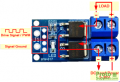
I needed one LED1 to turn on and turn off. Another one LED2 turns on when LED1 is off and goes off when LED1 is ON. The frequency of the pulses can be varied using the program. I dont switch the power supplies directly to LEDs I use this module:

High-Power-Dual-MOSFET-Switch-Module-Connections-Small.png

If I have a pwm I can just give it and switches the power ON and OFF to the LEDs.

Regarding the coding part, there was a separate PWM package for python developed by a third party developer that runs on python for Raspberry Pi. I suppose the functionality is limited and as of now since the issue is solved, we wouldnt go into it.
 
Last edited:

panic mode

Joined Oct 10, 2011
5,445
inverting state is what inverter does. this is an obvious choice from the begin.


you are all over the place and still did not explain what/why etc. this is an engineering forum so please do not be shy to use numbers.

why the LEDs need to be powered by synchronised (opposite phase)?
why two or more groups of LEDs need to be driven by one PWM channel? just use separate PWM for each to get full flexibility.
what are the LED specs? how many LEDs are being used at the same time? what is the pulsing frequency (or range)? what is the pulse duty cycle (or range)? if always 50%, why bother with PWM at all?
you said you are using Raspberry PI but never said which one, which exact GPIO pins, etc.

all raspberry pi support PWM in both hardware and software. hardware PWM is only available on some GPIO pins. failure to use correct GPIO for PWM is a design flaw. also using GPIO that supports PWM but is shared with other functions is a design flaw.
if you are using hardware PWM, your program just needs to initialize the PWM and can be on its way to do something else - this does not need constant attention as if doing software PWM.
and it does not matter if programming language is C or Python or whatever.

next, raspberry PI and PWM do not care if load is INTRARED LED or not, or what the IR wavelength is.
series resistor is sized according to supply voltage, LED current and LED forward voltage. when using only low duty cycle,
it is possible to take timing into consideration and push more current through the LEDs but based on what i've seen so far, this is not something you'd want.
if the LEDs only draw 1-2mA as you said before, you just need resistor. there is no need for mosfets.
if you are driving bunch of LEDs then suitable driver such as MOSFET is needed.

beware of gate capacitance as that, frequency, duty and gate threshold will dictate if Raspberry PI can drive this mosfet directly or some intermediate driver is needed. you posted (what a surprise) blurry image of some mosfet module, without specs. my guess it is something like AOD4148. that is a logic-level mosfet but it is optimised for 4.5-10V drive. to turn fully on higher voltage is needed. but the raspberry pi GPIOs are only 3.3V. so if using such mosfet unbuffered, you may want to keep the load low, for example under some 3A.

and to protect PI, it is not a bad idea to always use something to buffer GPIO.

as you can see, there is a lot one may want to consider and details matter. or you still want to play hide and seek?
 

Thread Starter

sab201

Joined Nov 18, 2023
322
panic mode,

Thanks for the detailed explanation.

For my knowledge, I have given the details that I can. I am not a design expert or highly technical person in electronic circuits. So pardon me if the details are insufficient.

Also I am only doing it part time as a home project/research, not a laboratory work with all high end equipments. I am using simple trial and error and keeping it as easy as possible without complicated circuits unless extremely necessary.
 

MrChips

Joined Oct 2, 2009
35,296
You still have not fully described your problem.

If you want to drive different LEDs, use one power supply and change the resistor value.

If your PWM signal is 50% why do you need PWM?
A steady logic level signal will work. You don’t need to invert the signal.
 

BobTPH

Joined Jun 5, 2013
11,677
I think he is trying to have two different wavelength LEDs alternate with a 50% duty cycle for each. If these are low power indicator LEDs a two transistor bistable would be all the circuitry needed.
 

Jon Chandler

Joined Jun 12, 2008
1,659
I am not a design expert or highly technical person in electronic circuits. So pardon me if the details are insufficient.
Explain WHAT you are trying to do, not HOW you think it could/should be done. This forum is filled with "design experts and highly technical people" who will likely have effective simple solutions once they understand the "WHAT."

It's clear that electronics isn't your strong point, so when you ask questions framed in a lack of understanding makes it really difficult to understand WHAT you're trying to do.

[As an example of your lack of understanding is your belief that you need multiple power supplies (different voltages) when a single voltage and an appropriate one cent resistor for each LED will work perfectly well and in fact better.]
 

Danko

Joined Nov 22, 2017
2,254
I am only doing it part time as a home project/research, not a laboratory work with all high end equipments. I am using simple trial and error and keeping it as easy as possible without complicated circuits unless extremely necessary.
First, that you should know:
The rate of biophotochemical reactions is determined by the mobility of ions in the cellular environment,
so the maximum frequency of light pulses, which varies depending on cellular structure, does not exceed 25 Hz.
Frequencies above 25 Hz have the same effect as continuous illumination.
You can check that in parameters of our vision.
New method to make money:
https://maysama.com/blogs/news/puls...HU3m1784kXNhwldJwNIVHb-muPaSHkFlrAsqDofNdV3e0
EDIT:
PDF added.
 

Attachments

Last edited:

AnalogKid

Joined Aug 1, 2013
12,294
The rate of biophotochemical reactions is determined by the mobility of ions in the cellular environment,
so the maximum frequency of light pulses, which varies depending on cellular structure, does not exceed 25 Hz.
Frequencies above 25 Hz have the same effect as continuous illumination.
fMRI research disagrees. 100 Hz flicker may not be perceivable consciously (except for movement artifacts), but it does make its way into the brain. This is one of the reasons that LCD screens are more fatiguing to watch long-term compared to CRTs.

ak
 
Top