Facebook
 Google
 GitHub
 Linkedin
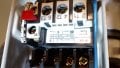
 I have just installed a used auto hoist, can anyone explain this switch and best way to wire it? I live quite a ways out and can't get an electrician for a month minimum. Took photos of the hydraulic plumbing but phone died before taking photo of electrical connections. Also seemed so easy that I did not draw it out. Doesn't seem so easy now! The motor ( in the pic) is a replacement 5hp (22 amp, SNG phase 220 motor), but the rest looks original. The Wht and Blk wires coming in to the switch from above is the normally open switch which when closed allows power to the motor to raise the hoist. The blk is connected to a rear terminal of this switch that I don't understand. (behind terminal 13). The Grn (ground) , Wht and Blk wires entering the switch box from below are from/to the motor. The power supply {not shown) is Blk, Wht and Ground. Some additional info; this switch has a red reset button, it has 4 black squares that I can't really call buttons between the 1 and 2 , 3 and 4, 5 and 6 and 13 and 14 #' .When powered I believe they move inward like when I push one all 4 will move but spring back out flush.The upper terminal lugs (from the left reset button which is labeled 96, then T3, T2 and T1. I do recall that the grn and bare wires were grounded( Duh), and the whites were mauretted together but I do not remember where the black power supply wire went. Is anyone familiar with this type of switch? Thank you and sorry for the perhaps unintelligible gibberish.
Last edited by a moderator:
")