Input protection with Schottky - what to do about this problem

Thread Starter

slowfuse

Joined Sep 7, 2010
16
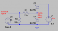
I am using the attached circuit to condition external signals for connection to a microcontroller. The Vcc is 3.3v. But, what happens is, that the voltage at the junction of the two schottkys is actually Vcc + the forward drop on the diodes which in some cases comes very close to the limit of 3.6v which the microcontroller is comfortable with. What should I change or which diodes should I select in order to have the input at Vcc? Thanks.
 

Attachments

I've gotta be honest, I'm not as strong as I should be with this stuff.

I don't understand why you have the 10k resistor in parallel with the diode, and I'm not sure why you tied it to VCC through the upper diode.

I will throw in that I remember reading that a diode needs certain current through it to stay in reverse breakdown.

Are you sure that the 10k resistor in parallel isn't shunting the diode and preventing it from reaching the required current to stay in reverse breakover? Is the 22K resistor limiting the current to the point that it can't stay in breakover?
 

Ghar

Joined Mar 8, 2010
655
I don't really get what you're trying to do there.

You have a 24V signal source and you're trying to connect it to a 3.3V micro?

What is that 24V and is it just 0 or 24 (logic) or is it a range?

The basic first step is that your resistors are in a strange configuration.
What that circuit does is it passes current from the 24V source into the 3.3V source through the 22k resistor and D2.

That probably isn't what you want.

The 10k resistor isn't really doing anything and D1 provides some reverse polarity protection.
 

eblc1388

Joined Nov 28, 2008
1,542
What should I change or which diodes should I select in order to have the input at Vcc? Thanks.
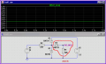
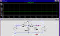
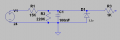
If you want to clamp the voltage to 3.3V, then you have to add another diode shown in the following image.

But you don't really need to use Schottky diode for D2 & D3. IN4148 is fine but do remember to use the same type of diode for D2 & D3.


Attachments

Thread Starter

slowfuse

Joined Sep 7, 2010
16
I don't really get what you're trying to do there.

You have a 24V signal source and you're trying to connect it to a 3.3V micro?

What is that 24V and is it just 0 or 24 (logic) or is it a range?
Yes, my micro is 3.3v (an MSP430) and I need to connect it to the "outside world".

The signals may be of two types, with voltages ranging from 5v to 30v actually:
a. Logical on/off signals (i.e. zero is off and some voltage is on)
b. square waves from zero to any voltage in this range, less than 1KHz
 

John P

Joined Oct 14, 2008
2,068
I'm a user of PIC processors, and if it were one of those, you really wouldn't need any protection components except the 22K resistor. The chip itself already has protection diodes to Vcc and Gnd, and as long as you don't exceed the current spec for those (1mA??) you can do what you want. Maybe your processor has a similar feature.
 

Thread Starter

slowfuse

Joined Sep 7, 2010
16
I'm a user of PIC processors, and if it were one of those, you really wouldn't need any protection components except the 22K resistor. The chip itself already has protection diodes to Vcc and Gnd, and as long as you don't exceed the current spec for those (1mA??) you can do what you want. Maybe your processor has a similar feature.
I use a MSP430, which is 3.3v and not 5v (not that I think it matters).
But your answer is strange to me, do you suggest that you would connect say a 50v signal to your PIC with just a 22k in series with the port???
 

John P

Joined Oct 14, 2008
2,068
Yes, that's right. With diodes in place, how can the voltage on the pins go higher than one diode drop above Vcc or lower than one diode drop below ground? It can't. And the resistor prevents any significant current from flowing. In fact Microchip's own application notes sometimes show input pins connected to high voltages with only a resistor in between.
 
Top