Input counter for Jeopardy type of game

Thread Starter

candro

Joined Aug 2, 2014
15
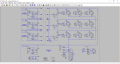
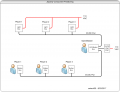
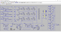
I currently have a Trivia game that I created using mechanical relays and switches. The game is played by 3 players, each having a switch that illuminates a light in front of them. The first person to press their switch locks out input from the other two players. The problem with this is that if the first person to press their switch gives the wrong answer I don't know who also tried to answer. I use a manual reset switch to clear the latch so another game can be played.

What I would like to have is a circuit that would remember the order in which each player pressed their switch.

Attached is a drawing for my current system.
 

Attachments

Marley

Joined Apr 4, 2016
502
First: how do you propose to display the order?
Colored lights - green - amber - red? this is OK for three players but not any more.
Numeric display - 7-segment displays for example - good for up to 9 players with a single digit for each player.

The best way to do this is with a simple micro-controller circuit but could be done with CMOS or even relay logic.
 

AnalogKid

Joined Aug 1, 2013
11,048
The general name for what you are doing is a "game show circuit". Conceptually, you need one complete circuit for each level of responding you want to capture. For example, if there are 8 players but you care only about the first 3 responders, then you need three, 8-wide game show circuits. The first circuit is enabled all the time. When it is triggered by the first response, it enables the second circuit. That one captures the second response and enables the third circuit.

Separate from latching the results is how they are displayed. As above, colored LEDs, numbers, etc.

ak
 

Marley

Joined Apr 4, 2016
502
Yes, one complete circuit for each player is a nice idea. Makes extending for any number of players easy. Also breaks the design down into manageable sections.

So lets say each player has a circuit board with a 7-segment display counter and a button. There will be a reset input which will connect to the quizmaster's reset button.

There will also have to be a signal to between the circuits tell other players circuits that they are not the first.

The reset button (connected to all circuits) clears the counter to zero and also clears a latch to blank the display on each circuit.
When a player presses his/her button the counter increments and sets the latch revealing the number. Once the latch is set the counter can no longer be incremented.
A link between all the circuits causes all the counters to increment when any of the players buttons are pressed - except those that are already lit.
 

Thread Starter

candro

Joined Aug 2, 2014
15
First: how do you propose to display the order?
Colored lights - green - amber - red? this is OK for three players but not any more.
Numeric display - 7-segment displays for example - good for up to 9 players with a single digit for each player.

The best way to do this is with a simple micro-controller circuit but could be done with CMOS or even relay logic.
Attached is a picture of the light box we use. If I could incorporate a small light in each box it would be perfect.
 

Attachments

Thread Starter

candro

Joined Aug 2, 2014
15
The general name for what you are doing is a "game show circuit". Conceptually, you need one complete circuit for each level of responding you want to capture. For example, if there are 8 players but you care only about the first 3 responders, then you need three, 8-wide game show circuits. The first circuit is enabled all the time. When it is triggered by the first response, it enables the second circuit. That one captures the second response and enables the third circuit.

Separate from latching the results is how they are displayed. As above, colored LEDs, numbers, etc.

ak
Thanks for the reference to the game show circuit.
 

AnalogKid

Joined Aug 1, 2013
11,048
How many levels of response do you want to indicate? Those look like standard house lights, so your options are bright, dim, and blinking. Also, how are you switching the AC power to the lights?

ak
 

Thread Starter

candro

Joined Aug 2, 2014
15
How many levels of response do you want to indicate? Those look like standard house lights, so your options are bright, dim, and blinking. Also, how are you switching the AC power to the lights?

ak
I would like to know the order in which the contestants push their N.O mushroom switch, either 1st, 2nd or 3rd Everything is 110 vac at the present time. I am not opposed to adding another small light to the light box shown in post #5 like green, amber, red. The power to the lights is based on the circuit attached to post #1.
 

AnalogKid

Joined Aug 1, 2013
11,048
This can be done with three more 110 VAC relays and three diodes. The three indication levels would be off (third place), dim (second place), and bright ( first response).

First, use the reference designator K for relays. Convert K1-K3 to 3PDT. The three extra poles are wired in parallel to switch 110 Vac to the second bank of relays. That bank is just like what you have now (DPDT relays), but the lines going back to the lights have a rectifier diode in series.

The first bank reset relay will reset everything with no additional connections to the second bank. Also, you need only one master reset set of contacts, not three. Or, with a normally closed switch, no MR relay at all.

There will be a few milliseconds between when the first button is pushed and the second bank is enabled to capture 2nd place. In that time, both remaining switches might be closed, confusing things. Logic gates have delays measured in nanoseconds, 1 million times faster, greatly reducing the chance of a draw.

ak
 

Thread Starter

candro

Joined Aug 2, 2014
15
This can be done with three more 110 VAC relays and three diodes. The three indication levels would be off (third place), dim (second place), and bright ( first response).

First, use the reference designator K for relays. Convert K1-K3 to 3PDT. The three extra poles are wired in parallel to switch 110 Vac to the second bank of relays. That bank is just like what you have now (DPDT relays), but the lines going back to the lights have a rectifier diode in series.

The first bank reset relay will reset everything with no additional connections to the second bank. Also, you need only one master reset set of contacts, not three. Or, with a normally closed switch, no MR relay at all.

There will be a few milliseconds between when the first button is pushed and the second bank is enabled to capture 2nd place. In that time, both remaining switches might be closed, confusing things. Logic gates have delays measured in nanoseconds, 1 million times faster, greatly reducing the chance of a draw.

ak
I like your idea, but I am having a hard time visualizing how it looks. Can you post a markup sketch of my drawing?
 

eetech00

Joined Jun 8, 2013
3,953
Hi

Here's a CD4000 IC version I cobbled together. I didn't breadboard it but it works in simulation.

The outputs of the FF's could be fitted with additional circuitry to drive indicators (Lamps, LED's, etc),
but I didn't want to go further unless your interested.
3PplayerJepardy.png

The circuit uses a pulse from each pushbutton to latch a FF. The FF that latches depends on the sequence of the input pulses and only three FF's will latch at a time to indicate 1st(G) 2nd(Y) and 3rd(R) place. An additional button provides a reset function.

EDIT: oops...I see I labeled the PB's wrong:(
The PBs should be labeled Player3, 2 ,1 from top to bottom..;)
 
Last edited:

Thread Starter

candro

Joined Aug 2, 2014
15
Hi

Here's a CD4000 IC version I cobbled together. I didn't breadboard it but it works in simulation.

The outputs of the FF's could be fitted with additional circuitry to drive indicators (Lamps, LED's, etc),
but I didn't want to go further unless your interested.
View attachment 133587

The circuit uses a pulse from each pushbutton to latch a FF. The FF that latches depends on the sequence of the input pulses and only three FF's will latch at a time to indicate 1st(G) 2nd(Y) and 3rd(R) place. An additional button provides a reset function.

EDIT: oops...I see I labeled the PB's wrong:(
The PBs should be labeled Player3, 2 ,1 from top to bottom..;)

This is really outstanding, thank you so much for your time and effort. I am fairly certain I could build this. I would use lamps at the push button stations and Green for 1st, Amber for 2nd, and Red for 3rd LEDS at the gamemaster control box with the reset. Do you have a BOM for the project? What voltage is used? I would need a blown up drawing to be able to see things more clearly. Thank you very, very much.
 

eetech00

Joined Jun 8, 2013
3,953
This is really outstanding, thank you so much for your time and effort. I am fairly certain I could build this. I would use lamps at the push button stations and Green for 1st, Amber for 2nd, and Red for 3rd LEDS at the gamemaster control box with the reset. Do you have a BOM for the project? What voltage is used? I would need a blown up drawing to be able to see things more clearly. Thank you very, very much.
Hi

The circuit can run between 3-15vdc. I'm using 12vdc for the simulation

Probably should design the Lamp/LED driver circuits and breadboard one channel before going forward. I have parts I could use to test.
So you would use three 110v AC Lamps at each player PB station, and three tri-color LEDs at the gamemaster control box? Is that correct?
What is the distance between the master control box and each player button box?
 
Last edited:

Thread Starter

candro

Joined Aug 2, 2014
15
Hi

The circuit can run between 3-15vdc. I'm using 12vdc for the simulation

Probably should design the Lamp/LED driver circuits and breadboard one channel before going forward. I have parts I could use to test.
So you would use three 110v AC Lamps at each player PB station, and three tri-color LEDs at the gamemaster control box? Is that correct?
What is the distance between the master control box and each player button box?
12 vdc would be fine I could change out the 110vac lamps for 12vdc if that would be easier. I could use 9 LEDS at the gamemaster box. One set of LEDS Green, Amber, and Red for each player. Distance would be about 20' from gamemaster box to each player button box.
 

Thread Starter

candro

Joined Aug 2, 2014
15
Hi

The circuit can run between 3-15vdc. I'm using 12vdc for the simulation

Probably should design the Lamp/LED driver circuits and breadboard one channel before going forward. I have parts I could use to test.
So you would use three 110v AC Lamps at each player PB station, and three tri-color LEDs at the gamemaster control box? Is that correct?
What is the distance between the master control box and each player button box?
12vdc is okay. I can change out the 110vac lamps at each station for 12vdc lamps if that would be easier. I could also use 9 LED's to keep the cost down. I would label the gamemaster box Player 1, Player 2, and Player 3. Under each player I could have a Green, Amber, and Red LED to designate their finish order. Distance from master box to player pushbutton box will be approximately 20'
 

eetech00

Joined Jun 8, 2013
3,953
12vdc is okay. I can change out the 110vac lamps at each station for 12vdc lamps if that would be easier. I could also use 9 LED's to keep the cost down. I would label the gamemaster box Player 1, Player 2, and Player 3. Under each player I could have a Green, Amber, and Red LED to designate their finish order. Distance from master box to player pushbutton box will be approximately 20'
Hi

Questions...

Players:
So...each player will have a button box with no lights...right?
Do the players need to see the lights? If so, where will the lights be located?

GameMaster:
The box will have a reset button.
The box will have three vertical columns of 3 lights, one column for each player, and are only visible for the gamemaster.
If these lights are only for the gamemaster, then these could be three tri-color LEDs, each labeled Player1, 2, 3.

I've modified the player button inputs at the gamemaster box to condition for long wires. DC supply voltage is 12v. See attached.

Regarding the audience lights (I'll just call them that meaning they're visible to everyone). If we choose DC to drive the lights then the current (amperes) demand on the DC supply goes up significantly. If we decide to go with 110 AC for audience lights, then we'll need to incorporate relays or optocouplers into the light drivers to provide isolation.

I'm still uncertain where the audience lights will be located for both the players and audience to see.
A diagram showing the physical layout (positioning) of the gamemaster box, player boxes, and lights would help.

Edit: I created and attached a layout diagram of what I think the physical layout will be. Please confirm.
 

Attachments

Last edited:

Thread Starter

candro

Joined Aug 2, 2014
15
Hi

Questions...

Players:
So...each player will have a button box with no lights...right?
Do the players need to see the lights? If so, where will the lights be located?

GameMaster:
The box will have a reset button.
The box will have three vertical columns of 3 lights, one column for each player, and are only visible for the gamemaster.
If these lights are only for the gamemaster, then these could be three tri-color LEDs, each labeled Player1, 2, 3.

I've modified the player button inputs at the gamemaster box to condition for long wires. DC supply voltage is 12v. See attached.

Regarding the audience lights (I'll just call them that meaning they're visible to everyone). If we choose DC to drive the lights then the current (amperes) demand on the DC supply goes up significantly. If we decide to go with 110 AC for audience lights, then we'll need to incorporate relays or optocouplers into the light drivers to provide isolation.

I'm still uncertain where the audience lights will be located for both the players and audience to see.
A diagram showing the physical layout (positioning) of the gamemaster box, player boxes, and lights would help.

Edit: I created and attached a layout diagram of what I think the physical layout will be. Please confirm.
In the photo on post #5 I show my Player Light Box. Directly behind each of the Player Light Boxes is a mushroom head pushbutton in a box that is wired to the Player Light Box. In my setup, player box #2 houses all of the relays and player light boxes #1 and #3. I can build a new gamemaster box to house the logic board(s), along with the LED's and the Master Reset. (see attached) I would prefer to stay with something like my attached drawing. Staying with the 110 vac bulb in existing audience light boxes would be great. Perhaps we can use solid state relays for the audience lights.
 

Thread Starter

candro

Joined Aug 2, 2014
15
Hi

Questions...

Players:
So...each player will have a button box with no lights...right?
Do the players need to see the lights? If so, where will the lights be located?

GameMaster:
The box will have a reset button.
The box will have three vertical columns of 3 lights, one column for each player, and are only visible for the gamemaster.
If these lights are only for the gamemaster, then these could be three tri-color LEDs, each labeled Player1, 2, 3.

I've modified the player button inputs at the gamemaster box to condition for long wires. DC supply voltage is 12v. See attached.

Regarding the audience lights (I'll just call them that meaning they're visible to everyone). If we choose DC to drive the lights then the current (amperes) demand on the DC supply goes up significantly. If we decide to go with 110 AC for audience lights, then we'll need to incorporate relays or optocouplers into the light drivers to provide isolation.

I'm still uncertain where the audience lights will be located for both the players and audience to see.
A diagram showing the physical layout (positioning) of the gamemaster box, player boxes, and lights would help.

Edit: I created and attached a layout diagram of what I think the physical layout will be. Please confirm.
The drawings look great! The physical layout looks good too!
 

eetech00

Joined Jun 8, 2013
3,953
In the photo on post #5 I show my Player Light Box. Directly behind each of the Player Light Boxes is a mushroom head pushbutton in a box that is wired to the Player Light Box. In my setup, player box #2 houses all of the relays and player light boxes #1 and #3. I can build a new gamemaster box to house the logic board(s), along with the LED's and the Master Reset. (see attached) I would prefer to stay with something like my attached drawing. Staying with the 110 vac bulb in existing audience light boxes would be great. Perhaps we can use solid state relays for the audience lights.
Hi

Ok...Based on what we've discussed, here's what I've come up with so far. See attached

The circuit is designed to drive relays. I thought about SSR's but I though they would be too expensive since we would need the ones that have a DC control but support an AC load. But its up to you.
I've also added a lamp test function. The lamp test button would be on the Gamemaster console. When the lamp test is pressed, the audience lights will sequencially light, G->Y->R, one at a time (for 1 second) for each box starting with light box 1, then light box 2, etc. The sequence will continue until the RESET button is pressed. This will let you test the bulbs one at a time.

Let me know what you think.
 

Attachments

Top