Inductors realized through Gyrator circuit

Thread Starter

shivashankar_p

Joined Nov 10, 2015
50
Hi,

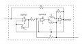
I constructed a Gyrator circuit (schematic Figure attached) to obtain a floating inductor (of value 0.7Henry). After completing the circuit on the breadboard, I put a resistor (1KOhm) in series with the Inductor and supplied a 1 Volt AC signal (100Hz) across the L-R element. Then, I measured the AC voltage across the resistor (to validate the Inductor) with a multimeter. The measured voltage matched the theoretical prediction, confirming the value of the realized the inductor. However, when I used the oscilloscope to view the Voltage signal across the resistor, it didn't match the prediction. As a matter of fact, the Voltage across the resistor still shows a signal with amplitude of 1V (while it should be 0.75V). I am confused by this. The multimeter gives the correct value, but the oscilloscope doesn't.

Could someone kindly comment as to what's going on here?

Interestingly, I also found that if I used the scope and the probe to measure the 5V supply from Arduino Uno, the value was around 2.8V. But, in the multimeter it was 5V.

Thanks,
Shiva
 

Attachments

Last edited:

Ya’akov

Joined Jan 27, 2019
9,170
I am using the TPP0500B probe for measurement. The specification says that it has 10X and 2X attenuation factor. Please find the image of the probe and the oscilloscope attached.
That probe should certainly not even be a factor. Just checking to see if the impedance difference between the DMM and the scope could be a cause.
 

Thread Starter

shivashankar_p

Joined Nov 10, 2015
50
That probe should certainly not even be a factor. Just checking to see if the impedance difference between the DMM and the scope could be a cause.
I have used the oscilloscope (with the probes) for many other measurements. Never had any issues. Only with this I have some issue. For this setup, I checked at different Voltages amplitudes and frequencies. For all cases, I have the same problem.
 

Thread Starter

shivashankar_p

Joined Nov 10, 2015
50
Presumably your DMM isn't grounded but your 'scope is? Is the op-amp supply grounded or floating?
I give +12V and -12 V to the OpAmp. Please look at the attached image; the red wire on the right and the black one on the extreme left are used to give the +12 V and -12V respectively to the OpAmps.

DMM isn't grounded. The scope might be, I am not sure.
 

Attachments

Last edited:

DickCappels

Joined Aug 21, 2008
10,187
How you calculated the voltage across the resistor. I guess that is what you refer to as the L-R circuit analytical expressions. That might offer a clue. Usually I would rely on the reading on the scope over that on an AV voltmeter.

What frequency are you driving the circuit with?
 

Thread Starter

shivashankar_p

Joined Nov 10, 2015
50
How you calculated the voltage across the resistor. I guess that is what you refer to as the L-R circuit analytical expressions. That might offer a clue. Usually I would rely on the reading on the scope over that on an AV voltmeter.

What frequency are you driving the circuit with?
The analytical expressions are those
How you calculated the voltage across the resistor. I guess that is what you refer to as the L-R circuit analytical expressions. That might offer a clue. Usually I would rely on the reading on the scope over that on an AV voltmeter.

What frequency are you driving the circuit with?
The driving frequency is 100Hz. Please find the attached image for the analytical expressions. I have validated these expressions with circuit simulations in Simulink.

Regarding the comment on the measurement through DMM, I get the exact prediction with the MM. Even with different driving frequencies and the Resistor values, the measurement made from the DMM matches the analytical predictions.
 

Attachments

Thread Starter

shivashankar_p

Joined Nov 10, 2015
50
What does that black 2-conductor cable on the ground terminal connect to? Your schematic shows no ground connection.
The black cable (in the middle) doesn't connect to the circuit. It was just left there. Only the red (right) and black (left) cable are connected as sources.

Yes, the schematic has no ground connection.
 

Thread Starter

shivashankar_p

Joined Nov 10, 2015
50
The black cable (in the middle) doesn't connect to the circuit. It was just left there. Only the red (right) and black (left) cable are connected as sources.

Yes, the schematic has no ground connection.
What does that black 2-conductor cable on the ground terminal connect to? Your schematic shows no ground connection.
Interestingly, I also found that if I used the scope and the probe to measure the 5V supply from Arduino Uno, the value was around 2.8V. But, in the multimeter it was 5V.
 

Thread Starter

shivashankar_p

Joined Nov 10, 2015
50
That probe should certainly not even be a factor. Just checking to see if the impedance difference between the DMM and the scope could be a cause.
Interestingly, I also found that if I used the scope and the probe to measure the 5V supply from Arduino Uno, the value was around 2.8V. But, in the multimeter it was 5V.
 

Ya’akov

Joined Jan 27, 2019
9,170
If the signal seems to be off, even with the compensation calibrator you can try the signal path calibration in the Utility menu.

1645787337918.png
 

drjohsmith

Joined Dec 13, 2021
852
One other thing to consider,
is where are you "earthing" the scope probe to to take a measurement ?

The DVM is measuring a floating signal.
the scope is measuring relative to earth,

Either us a differential probe ,
or use two probes,
one to either side of the resistor
with the gnd of the probes connected to power gnd of the circuit.
and measure the difference ( one use of the A - B function of the scope )
 
Top