 Facebook
 Google
 GitHub
 Linkedin
Hello Mr. Al, thanks for the info. I have got a better understanding of the inductor now. I however still have little doubts. For a capacitor, we know that the voltage cant change immediately because that means charge should move at zero time (dv/dt= inf) which mean inf current, which isnt possible. This also contradicts the conservation of energy, I believe. From what I tried to gather, energy can't just jump states. This similar explanation allowed me to understand inductors better. I get that inductors too cant allow current to change immediately due to lenz alw. This also can be explained with the enrgy LI^2/2 the magnetic field holds similar to a capacitor. my new doubt however has emerged. Faraday stated that an inductor opposes change in current by inducing voltage (back emf). now lets say an inductor initially having zero current flowing through it is connected immediately to a voltage source..how would it behave..? since there is no current flowing through it what would the voltage across it be? what would be the polarity. And my biggest question is this: since the back emf opposes the change in current, shouldnt the current never even begin to rise in an inductor? this confusion caused me to get confused with the capacitor also as now i wonder how a capacitor maintains constant voltage across its terminals. if a capacitor is connected across a voltage at t=0, what would the voltage across its terinals be immediately at t=0 or after sometime..i understand that the voltage slowly rises..due to the presence of impedance the current is limited..but if we assume ideal cases how would the inductor and capacitor behave? please give me some idea about it if you can. It would be extremely helpful!!Hi,
There is a very simple way to understand how an inductor works but you do have to already know how a capacitor works and how a voltage source works and how a current source works. Alternately, you just have to accept the "smoothing" analogy.
If you know how a capacitor works then you know that the capacitor tries to keep the voltage constant, which means for a short time the capacitor looks like a battery!
Well, an inductor tries to keep the current constant, which means for a short time the inductor looks like a current source!
HOW THIS AFFECTS FILTERING
Well, if we have a device that tries to keep the voltage constant, that causes a smoothing action of the voltage (aka a voltage filter). That's a capacitor.
If we have another device that tries to keep the current constant, that causes a smoothing action of the current (aka a current filter) . That's an inductor.
Put these two together and we have a smoothing action on both the voltage and the current, and that's a filter. In particular, a low pass filter. This is desirable for a rectifier circuit because the output of the diodes is not smooth it is pulsating. We want a smooth DC output so we use a capacitor and sometimes an inductor with that also so we get good filtering action. It's still not perfect, but it helps a lot.
REAL WORLD EXAMPLES
With a capacitor, if we had 12.4 volts at a node at a certain time, at a very short time later we would still have 12.4 volts. It will decrease later but we don't worry about that just yet.
With an inductor, if we had 1.1 amps flowing at a certain time, at a very short time later we would still have 1.1 amps flowing. It will decrease later but we don't worry about that just yet.
As to the decreases "later", we choose the value of the component so that we do not get too much of a decrease later.
We can go deeper into this with examples or with math. It depends how well you want to understand this.
Inductor for Filtering Full wave Recitifed output??
- Thread starter TheticVoyage630
- Start date
Scroll to continue with content
im sorry mr smith if i offended you, never my intention. I wasnt able to receive formal education at a part of my higher education and hence i had to self study, therefore i have some gaps in my understanding of the topics. im sorry if i offended you.thank you for the insult.
I can explain to you down to the magnetic spin of the atoms in the inductor , but your not listening to me.
the way we teach this, is as I've mentioned, and you have e failed to do, we'd mark you as an E ..
draw the circuit ,
draw the currents and voltage at each node of the circuit,
then we can discuss .
now days we do that in simulation programs , but as you want the intuitive understanding , then pencil and paper is the best, simulation tends to cloud intuitive understanding
How could it be anything but the voltage and polarity of the applied source?lets say an inductor initially having zero current flowing through it is connected immediately to a voltage source..how would it behave..? since there is no current flowing through it what would the voltage across it be?
The back emf does oppose the change in current but it doesn't stop it, so the current will change with an applied voltage.since the back emf opposes the change in current, shouldnt the current never even begin to rise in an inductor?
Oppose doesn't mean stop. It just means the back emf from the changing inductor current equals the applied voltage.
This back emf is generated by the changing magnetic field of the inductance and that only occurs when the current is changing (i.e. increasing with the applied voltage).
Thus the instant the voltage is applied, the current starts increasing, generating a changing magnetic field that provides the back emf.
Basically the inductance is converting the energy of the voltage and current into a magnetic field which stores the energy.
So if the inductor current is not changing, there is no back emf and the magnetic field energy is constant.
That make sense now?
Last edited:
drjohsmith
- Joined Dec 13, 2021
- 1,613
as you say, capacitance is linked to dv/ dt.Hello Mr. Al, thanks for the info. I have got a better understanding of the inductor now. I however still have little doubts. For a capacitor, we know that the voltage cant change immediately because that means charge should move at zero time (dv/dt= inf) which mean inf current, which isnt possible. This also contradicts the conservation of energy, I believe. From what I tried to gather, energy can't just jump states. This similar explanation allowed me to understand inductors better. I get that inductors too cant allow current to change immediately due to lenz alw. This also can be explained with the enrgy LI^2/2 the magnetic field holds similar to a capacitor. my new doubt however has emerged. Faraday stated that an inductor opposes change in current by inducing voltage (back emf). now lets say an inductor initially having zero current flowing through it is connected immediately to a voltage source..how would it behave..? since there is no current flowing through it what would the voltage across it be? what would be the polarity. And my biggest question is this: since the back emf opposes the change in current, shouldnt the current never even begin to rise in an inductor? this confusion caused me to get confused with the capacitor also as now i wonder how a capacitor maintains constant voltage across its terminals. if a capacitor is connected across a voltage at t=0, what would the voltage across its terinals be immediately at t=0 or after sometime..i understand that the voltage slowly rises..due to the presence of impedance the current is limited..but if we assume ideal cases how would the inductor and capacitor behave? please give me some idea about it if you can. It would be extremely helpful!!
an inductor is linked to -di / dt
in your example, inductor streight across a voltage source, emf, di/it is zero , so current flow can be infinite, limited by inductor resistance and voltage source .
but.
as soon as current starts to flow though , at 1 delta, a back empty is generated , which is in opposition to the applied emf , due to the -ve sign. this lowers apparent voltage across the inductor to near zero,
as before, draw your circuit, the current and voltage waveforms you expect, and we can comment .
Hello again,Hello Mr. Al, thanks for the info. I have got a better understanding of the inductor now. I however still have little doubts. For a capacitor, we know that the voltage cant change immediately because that means charge should move at zero time (dv/dt= inf) which mean inf current, which isnt possible. This also contradicts the conservation of energy, I believe. From what I tried to gather, energy can't just jump states. This similar explanation allowed me to understand inductors better. I get that inductors too cant allow current to change immediately due to lenz alw. This also can be explained with the enrgy LI^2/2 the magnetic field holds similar to a capacitor. my new doubt however has emerged. Faraday stated that an inductor opposes change in current by inducing voltage (back emf). now lets say an inductor initially having zero current flowing through it is connected immediately to a voltage source..how would it behave..? since there is no current flowing through it what would the voltage across it be? what would be the polarity. And my biggest question is this: since the back emf opposes the change in current, shouldnt the current never even begin to rise in an inductor? this confusion caused me to get confused with the capacitor also as now i wonder how a capacitor maintains constant voltage across its terminals. if a capacitor is connected across a voltage at t=0, what would the voltage across its terinals be immediately at t=0 or after sometime..i understand that the voltage slowly rises..due to the presence of impedance the current is limited..but if we assume ideal cases how would the inductor and capacitor behave? please give me some idea about it if you can. It would be extremely helpful!!
First I'd like to say that it is nice to see that you are interested in this and from your replies I can see that you have the mind to comprehend all this and that means that you'll soon get the idea of what is happening in an inductor.
I have seen that many people who first encounter inductors usually have some experience with capacitors, so it's a good place to start. You have already seen that if the capacitor with an impedance like a resistor has a change in current, the voltage will rise slowly. The capacitor does not allow the voltage to change in zero time because the impedance of the capacitor itself is zero at t=0 (no time has passed yet). Now as time does pass, the capacitor starts to charge, and initially it is ramp. The voltage climbs up say 0.1v, 0.2v, 0.3v, 0.4v, etc., and that's an approximation for short times but not zero time. In fact, one definition of the capacitor action is:
i=C*dv/dt
If we solve this for dv (which we can just call the voltage for now) we get:
i*dt/C=dv
or
dv=i*dt/C
and we can look at that for short time periods as:
v=i*t/C
when t is a short time and the initial voltage 'v' is zero.
Now we can ask, what would it take to get the voltage to never change, no matter what, because that is part of the question you are looking at.
Well, if 'i' was some arbitrary value like 0.1 amps and t was nonzero and C was some common value, we would still see v change eventually. But if we look on the left at 'C' it happens to be in the denominator. That means the bigger we make 'C', the slower 'v' will increase. So what if we make 'C' very, very ,very large. Well, it would make it look like, for a while, that 'v' was not changing at all. So making C extremely large would make it look like 'v' never changes (for a time).
Looking at the inductor, we see this similar relationship:
v=L*di/dt
and solving for di we get:
di=v*dt/L
or simplified:
i=v*t/L
so we see the same sort of action, except now it's the current that increases very slowly with very large L.
Now as to the back EMF, that's another story. We don't really have to consider that in circuit analysis most of the time. That's because that invokes the physical aspects of the inductor and pure circuit analysis is a little different than a full physical description. There is a simpler way to understand this though, and that is that the back EMF causes a temporary effect in the inductor. It slows down the rise of current as the last expression above shows. The 'back EMF' opposes the change, but it does not keep it from gradually increasing. So we can say with more precision that the back EMF limits the speed at which the current can change.
A related idea concerning back EMF is that there is NO back EMF unless the current is CHANGING. So in a way, the current has to be already changing in order to get back EMF. If we look above again, we see the back EMF on the left side of v=L*di/dt except if we want to be careful we change the sign v=-L*di/dt but don't worry too much about that sign yet.
Ok, so we apply 10 volts across an inductor, and we do not see any current for a very very short time (in reality it would START to change). So now we see that the back EMF is -10 volts, and that 'opposes' the 10 volts applied so we get no current flow just yet. As time progresses, the voltage across the inductor starts to decrease, and so now the back EMF is not opposing as much as it was before.
A key point is that there is no back EMF unless the current is changing. When the constant voltage source is first connected across the inductor, there is zero current, but there is still a change in current and that change in current is a changing current so we get back EMF immediately.
If you ask me, we should not worry too much about back EMF in an inductor. That's because it all happens inside the inductor and we don't have to really calculate it in circuit analysis in order to do an analysis of a circuit for voltage and currents. It's more important to understand in motors. For some reason it is (or at least was) taught in schools in order to show some reason for no current flowing in an inductor. I think it's not a good idea myself, as the expression above shows the whole deal without any back EMF.
Perhaps a shorter explanation is that as the current changes the field increases and an increasing field creates a voltage in the opposite direction to the applied voltage. So we can say that the inductor creates it's own opposing voltage due to the increasing field.
It might be good to look at two coils where one generates the field and the other generates a voltage due to that field. If we had ideal conditions the voltage in the second coil would be the same in the first coil just of opposite polarity. If they were put in series, the voltage measured across both coils would be zero.
For now, you should concentrate on the definiton v=L*di/dt as that explains it all without the need to refer to back EMF. I know that curiosity gets the better part of us sometimes though as we end up wanting to know more about everything including back EMF
")
It's kind of funny because we often talk about back EMF doing this and back EMF doing that, but we seldom calculate it outright. It's only in some applications that it's actually good to know like with motors, where knowing about the back EMF can allow the design of a speed regulating system.
drjohsmith
- Joined Dec 13, 2021
- 1,613
I like this explanation very muchHello again,
First I'd like to say that it is nice to see that you are interested in this and from your replies I can see that you have the mind to comprehend all this and that means that you'll soon get the idea of what is happening in an inductor.
I have seen that many people who first encounter inductors usually have some experience with capacitors, so it's a good place to start. You have already seen that if the capacitor with an impedance like a resistor has a change in current, the voltage will rise slowly. The capacitor does not allow the voltage to change in zero time because the impedance of the capacitor itself is zero at t=0 (no time has passed yet). Now as time does pass, the capacitor starts to charge, and initially it is ramp. The voltage climbs up say 0.1v, 0.2v, 0.3v, 0.4v, etc., and that's an approximation for short times but not zero time. In fact, one definition of the capacitor action is:
i=C*dv/dt
If we solve this for dv (which we can just call the voltage for now) we get:
i*dt/C=dv
or
dv=i*dt/C
and we can look at that for short time periods as:
v=i*t/C
when t is a short time and the initial voltage 'v' is zero.
Now we can ask, what would it take to get the voltage to never change, no matter what, because that is part of the question you are looking at.
Well, if 'i' was some arbitrary value like 0.1 amps and t was nonzero and C was some common value, we would still see v change eventually. But if we look on the left at 'C' it happens to be in the denominator. That means the bigger we make 'C', the slower 'v' will increase. So what if we make 'C' very, very ,very large. Well, it would make it look like, for a while, that 'v' was not changing at all. So making C extremely large would make it look like 'v' never changes (for a time).
Looking at the inductor, we see this similar relationship:
v=L*di/dt
and solving for di we get:
di=v*dt/L
or simplified:
i=v*t/L
so we see the same sort of action, except now it's the current that increases very slowly with very large L.
Now as to the back EMF, that's another story. We don't really have to consider that in circuit analysis most of the time. That's because that invokes the physical aspects of the inductor and pure circuit analysis is a little different than a full physical description. There is a simpler way to understand this though, and that is that the back EMF causes a temporary effect in the inductor. It slows down the rise of current as the last expression above shows. The 'back EMF' opposes the change, but it does not keep it from gradually increasing. So we can say with more precision that the back EMF limits the speed at which the current can change.
A related idea concerning back EMF is that there is NO back EMF unless the current is CHANGING. So in a way, the current has to be already changing in order to get back EMF. If we look above again, we see the back EMF on the left side of v=L*di/dt except if we want to be careful we change the sign v=-L*di/dt but don't worry too much about that sign yet.
Ok, so we apply 10 volts across an inductor, and we do not see any current for a very very short time (in reality it would START to change). So now we see that the back EMF is -10 volts, and that 'opposes' the 10 volts applied so we get no current flow just yet. As time progresses, the voltage across the inductor starts to decrease, and so now the back EMF is not opposing as much as it was before.
A key point is that there is no back EMF unless the current is changing. When the constant voltage source is first connected across the inductor, there is zero current, but there is still a change in current and that change in current is a changing current so we get back EMF immediately.
If you ask me, we should not worry too much about back EMF in an inductor. That's because it all happens inside the inductor and we don't have to really calculate it in circuit analysis in order to do an analysis of a circuit for voltage and currents. It's more important to understand in motors. For some reason it is (or at least was) taught in schools in order to show some reason for no current flowing in an inductor. I think it's not a good idea myself, as the expression above shows the whole deal without any back EMF.
Perhaps a shorter explanation is that as the current changes the field increases and an increasing field creates a voltage in the opposite direction to the applied voltage. So we can say that the inductor creates it's own opposing voltage due to the increasing field.
It might be good to look at two coils where one generates the field and the other generates a voltage due to that field. If we had ideal conditions the voltage in the second coil would be the same in the first coil just of opposite polarity. If they were put in series, the voltage measured across both coils would be zero.
For now, you should concentrate on the definiton v=L*di/dt as that explains it all without the need to refer to back EMF. I know that curiosity gets the better part of us sometimes though as we end up wanting to know more about everything including back EMF
It's kind of funny because we often talk about back EMF doing this and back EMF doing that, but we seldom calculate it outright. It's only in some applications that it's actually good to know like with motors, where knowing about the back EMF can allow the design of a speed regulating system.
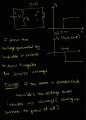
I hope this makes sense. I hope dr smith is able to understand my quandary better. Mr. Als response was very helpful. Thank you very much Mr. Al. But I still wasnt able to get my question answered. It must be due to a communication gap. I hope these images explain my doubts better. I however will reiterate my doubts in text too. Im very sorry to keep nagging you all regarding this.
So my understanding of capacitance--> it is a component that accumulates charges on its terminals. the amount of charge it can acculumate depends on its property called capacitance. Now, when a capacitor is connected to a voltage source in parallel (assuming ideal capacitor and ideal source and ideal wires) the capcitor follows the voltage source due to KVL. This means if the voltage source jumps a certain voltage level at a time, the capacitor should also jump due to ideal conditions...if the conditions werent ideal then there would be a voltage drop across the source impedance thus cauasing the voltage to build slowly, but if we consider ideal conditions this is what should happen. However this cannot happen due to conservation of energy as energy cannot just jump from one level to another.
So here raises one of my doubts..If we assume "ideal conditions", would a capacitor still smooth out the voltage spike in adherence to conservation of energy or follow KVL and follow the voltage spike?
My understanding of inductors--> inductors are wires round into a coil. When current flows throufh them (a steady currrent) they establish a magnetic filed around themselves with a certain amount of enrgy li^2/2. When inductors are subjected to a change in current, they oppose it due laws of electromagnetism and utilize the energy of the magnetic field to negate this change of current. That is suppose the current through an inductor increases..the magnetic field increases itself a bit to negate this change in current or if current through an inductor decreases, the magnetic field collapses a bit to establish the previous current flow going. This is done by establishing an emf across the inductor. ( this is my understanding as of now, please do correct me if I am wrong anywhere. Any corrections are encouraged. Do help me and share your views and thoughts to help me understand this better). As same with a capacitor, an inductor also doesnt allow immediate changes in current due to conservation of energy .
So here raises my doubt: Suppose an ideal inductor (zero resistance) is connected to a DC Voltage source with a switch. Initially the switch is off. Once the switch turns on due to KVL the voltage across the inductor is the source voltage. Since the inductor is a wire and we are assuming an ideal wire with no resistance, the current through it should be infinity. Since this is a massive change the back emf generated is also massive and it prevents this change of current to occur. Now gradually however current does start to flow in the inductor..how is that possible? is the back emf present only momentarily? if yes why? if no why? how does the current through the inductor increase if there is a response to oppose its change? Also if the current through an inductor is increasing, doesnt it mean its changing with time..doesnt that mean an emf should be generated to oppose its change? how does it keep overpowering this back emf to keep increasing? I hope I was able to articulate my doubts better. Please do share your views and help me with this. Any help is appreciated !!
Dr smith, would you atleast give me a C for drawing what i meant now?
Attachments
-
 257.6 KB Views: 6
 -
 300.8 KB Views: 6
 -
 224 KB Views: 5
drjohsmith
- Joined Dec 13, 2021
- 1,613
As explained , above by @MrAl very well.I hope this makes sense. I hope dr smith is able to understand my quandary better. Mr. Als response was very helpful. Thank you very much Mr. Al. But I still wasnt able to get my question answered. It must be due to a communication gap. I hope these images explain my doubts better. I however will reiterate my doubts in text too. Im very sorry to keep nagging you all regarding this.
So my understanding of capacitance--> it is a component that accumulates charges on its terminals. the amount of charge it can acculumate depends on its property called capacitance. Now, when a capacitor is connected to a voltage source in parallel (assuming ideal capacitor and ideal source and ideal wires) the capcitor follows the voltage source due to KVL. This means if the voltage source jumps a certain voltage level at a time, the capacitor should also jump due to ideal conditions...if the conditions werent ideal then there would be a voltage drop across the source impedance thus cauasing the voltage to build slowly, but if we consider ideal conditions this is what should happen. However this cannot happen due to conservation of energy as energy cannot just jump from one level to another.
So here raises one of my doubts..If we assume "ideal conditions", would a capacitor still smooth out the voltage spike in adherence to conservation of energy or follow KVL and follow the voltage spike?
My understanding of inductors--> inductors are wires round into a coil. When current flows throufh them (a steady currrent) they establish a magnetic filed around themselves with a certain amount of enrgy li^2/2. When inductors are subjected to a change in current, they oppose it due laws of electromagnetism and utilize the energy of the magnetic field to negate this change of current. That is suppose the current through an inductor increases..the magnetic field increases itself a bit to negate this change in current or if current through an inductor decreases, the magnetic field collapses a bit to establish the previous current flow going. This is done by establishing an emf across the inductor. ( this is my understanding as of now, please do correct me if I am wrong anywhere. Any corrections are encouraged. Do help me and share your views and thoughts to help me understand this better). As same with a capacitor, an inductor also doesnt allow immediate changes in current due to conservation of energy .
So here raises my doubt: Suppose an ideal inductor (zero resistance) is connected to a DC Voltage source with a switch. Initially the switch is off. Once the switch turns on due to KVL the voltage across the inductor is the source voltage. Since the inductor is a wire and we are assuming an ideal wire with no resistance, the current through it should be infinity. Since this is a massive change the back emf generated is also massive and it prevents this change of current to occur. Now gradually however current does start to flow in the inductor..how is that possible? is the back emf present only momentarily? if yes why? if no why? how does the current through the inductor increase if there is a response to oppose its change? Also if the current through an inductor is increasing, doesnt it mean its changing with time..doesnt that mean an emf should be generated to oppose its change? how does it keep overpowering this back emf to keep increasing? I hope I was able to articulate my doubts better. Please do share your views and help me with this. Any help is appreciated !!
Dr smith, would you atleast give me a C for drawing what i meant now?
Well, once you connect an ideal voltage source across an inductor (with no current flow yet) the current immediately starts to increase. In the theory of what we call the "back EMF", the back EMF exactly equals the applied voltage. So we might think of this as two voltage sources (one we can't see inside the inductor, the back EMF) and the other the applied voltage, and they are in series and of opposite polarity. This means that in theory the 'voltage inside' the inductor might be thought of as being zero. So the question becomes, how does a zero voltage create any current at all.I hope this makes sense. I hope dr smith is able to understand my quandary better. Mr. Als response was very helpful. Thank you very much Mr. Al. But I still wasnt able to get my question answered. It must be due to a communication gap. I hope these images explain my doubts better. I however will reiterate my doubts in text too. Im very sorry to keep nagging you all regarding this.
So my understanding of capacitance--> it is a component that accumulates charges on its terminals. the amount of charge it can acculumate depends on its property called capacitance. Now, when a capacitor is connected to a voltage source in parallel (assuming ideal capacitor and ideal source and ideal wires) the capcitor follows the voltage source due to KVL. This means if the voltage source jumps a certain voltage level at a time, the capacitor should also jump due to ideal conditions...if the conditions werent ideal then there would be a voltage drop across the source impedance thus cauasing the voltage to build slowly, but if we consider ideal conditions this is what should happen. However this cannot happen due to conservation of energy as energy cannot just jump from one level to another.
So here raises one of my doubts..If we assume "ideal conditions", would a capacitor still smooth out the voltage spike in adherence to conservation of energy or follow KVL and follow the voltage spike?
My understanding of inductors--> inductors are wires round into a coil. When current flows throufh them (a steady currrent) they establish a magnetic filed around themselves with a certain amount of enrgy li^2/2. When inductors are subjected to a change in current, they oppose it due laws of electromagnetism and utilize the energy of the magnetic field to negate this change of current. That is suppose the current through an inductor increases..the magnetic field increases itself a bit to negate this change in current or if current through an inductor decreases, the magnetic field collapses a bit to establish the previous current flow going. This is done by establishing an emf across the inductor. ( this is my understanding as of now, please do correct me if I am wrong anywhere. Any corrections are encouraged. Do help me and share your views and thoughts to help me understand this better). As same with a capacitor, an inductor also doesnt allow immediate changes in current due to conservation of energy .
So here raises my doubt: Suppose an ideal inductor (zero resistance) is connected to a DC Voltage source with a switch. Initially the switch is off. Once the switch turns on due to KVL the voltage across the inductor is the source voltage. Since the inductor is a wire and we are assuming an ideal wire with no resistance, the current through it should be infinity. Since this is a massive change the back emf generated is also massive and it prevents this change of current to occur. Now gradually however current does start to flow in the inductor..how is that possible? is the back emf present only momentarily? if yes why? if no why? how does the current through the inductor increase if there is a response to oppose its change? Also if the current through an inductor is increasing, doesnt it mean its changing with time..doesnt that mean an emf should be generated to oppose its change? how does it keep overpowering this back emf to keep increasing? I hope I was able to articulate my doubts better. Please do share your views and help me with this. Any help is appreciated !!
Dr smith, would you atleast give me a C for drawing what i meant now?
The answer is that voltage is sometimes independent of current. In a resistance, this is not true, but in a reactive component like an inductor, it is very often true. As a second example, all we have to do is look at an AC source that powers an inductor and we will see the current out of phase with the voltage, and this happens many times per second even at a low frequency like line frequency (50Hz, 60Hz, 100Hz, 400Hz). That means there are many times where the voltage is zero but the current is nonzero, and can even be hundreds of amperes. So this is not really that special, but it takes a thought process that brings us away from thinking about a pure resistance and a voltage driving that resistance where we always see a strong linear relationship between current and voltage where one is always present when the other is too.
This and other phenomena like this leads me to sometimes say that current and voltage by themselves are almost not even real, or that we don't get any useful energy without having them both present. There are however times when a current or voltage alone may be useful though without expending any energy. We don't have to get into this aspect of it though.
Hello All, I think I have finally understood the quagmire. It seems I was lost with the definitions and wordings. Please allow me to tell you what I have garnered so far. Do tell me if I am in the right path or not. Any feedback is appreciated and most welcomed.
I first jump to the explanation of back emf. Farday stated that any change in current establishes a voltage across its terminals (it= inductor) such that it negates the change in current. This voltage is called back emf as it opposes this change. However , this is symmetric. ie here the change in current is the cause and the effect is the voltage across the inductor terminals. In my condition however, the effect and cause are reversed. The cause is the voltage across the terminals..and the effect because of this cause is the rate of change in current in the inductor. I believe in circuit analysis, using the term "BACK EMF" is confusing and I should probably just stick to voltages and currents (as im typing this i realise this is what Mr.Al said previously). Back emf would make more sense to use if I was talking about changes in current etc like in motors (this is exactly what Mr.Al was saying, i just couldnt comprehend it then, it makes more sense to me now)
This is what I understood and I think it makes sense to me. We set the voltage across the inductor terminals according to KVL (which equals tthe source voltage) and to satisfy faradays laws, a rate of current is established accrding to this voltage in the inductor. Am i correct in this understanding or is there any flaw? do tell me as i feel i have made some concepts clear with this understanding.
PS> many people might say this is what we were saying in the first place and you are probably right. I just took a lot of time to comprehend it. I hope you excuse me for my slow learning. Thank you all once again.
That sounds about right.Hello All, I think I have finally understood the quagmire. It seems I was lost with the definitions and wordings. Please allow me to tell you what I have garnered so far. Do tell me if I am in the right path or not. Any feedback is appreciated and most welcomed.
I first jump to the explanation of back emf. Farday stated that any change in current establishes a voltage across its terminals (it= inductor) such that it negates the change in current. This voltage is called back emf as it opposes this change. However , this is symmetric. ie here the change in current is the cause and the effect is the voltage across the inductor terminals. In my condition however, the effect and cause are reversed. The cause is the voltage across the terminals..and the effect because of this cause is the rate of change in current in the inductor. I believe in circuit analysis, using the term "BACK EMF" is confusing and I should probably just stick to voltages and currents (as im typing this i realise this is what Mr.Al said previously). Back emf would make more sense to use if I was talking about changes in current etc like in motors (this is exactly what Mr.Al was saying, i just couldnt comprehend it then, it makes more sense to me now)
This is what I understood and I think it makes sense to me. We set the voltage across the inductor terminals according to KVL (which equals tthe source voltage) and to satisfy faradays laws, a rate of current is established accrding to this voltage in the inductor. Am i correct in this understanding or is there any flaw? do tell me as i feel i have made some concepts clear with this understanding.
PS> many people might say this is what we were saying in the first place and you are probably right. I just took a lot of time to comprehend it. I hope you excuse me for my slow learning. Thank you all once again.
We can solve the ideal (no resistance in series) inductor expression:
v=L*di/dt
for di/dt and get:
di/dt=v/L
If we apply v=1v to an inductor L=2H we see that:
di/dt=v/L
comes out to:
di/dt=1/2
This means that for the first second we will see 0.5 amps though the inductor, and after the next second we will see another 0.5 amps so the total will be 1.0 amps, and after the third second t=3 we will see i=1.5 amps, and at t=4 we will see i=2.0 amps, etc., etc. This means we end up with:
i=t*v/L
Since we may have had some current to begin with, we can add that to the right side to get:
i=t*v/L+i0
where i0 is the starting current which is also called the initial current or the initial condition.
This is very simple to think about too. In the above, if we had 1.5 amps to start with and we waited one more second, we would get:
i=1*1/2+1.5=0.5+1.5
so:
i=2.0 amps
same as before except we only had to wait 1 second because there was already 1.5 amps flowing through the inductor when we started.
One of the main differences between this and a resistor is we encounter a dependency on time 't' now. With a resistor we don't have that kind of dependency. This is where differential equations come in which allows us to solve a lot of these kinds of circuits with other components too.
drjohsmith
- Joined Dec 13, 2021
- 1,613
your humility does you credit .Hello All, I think I have finally understood the quagmire. It seems I was lost with the definitions and wordings. Please allow me to tell you what I have garnered so far. Do tell me if I am in the right path or not. Any feedback is appreciated and most welcomed.
I first jump to the explanation of back emf. Farday stated that any change in current establishes a voltage across its terminals (it= inductor) such that it negates the change in current. This voltage is called back emf as it opposes this change. However , this is symmetric. ie here the change in current is the cause and the effect is the voltage across the inductor terminals. In my condition however, the effect and cause are reversed. The cause is the voltage across the terminals..and the effect because of this cause is the rate of change in current in the inductor. I believe in circuit analysis, using the term "BACK EMF" is confusing and I should probably just stick to voltages and currents (as im typing this i realise this is what Mr.Al said previously). Back emf would make more sense to use if I was talking about changes in current etc like in motors (this is exactly what Mr.Al was saying, i just couldnt comprehend it then, it makes more sense to me now)
This is what I understood and I think it makes sense to me. We set the voltage across the inductor terminals according to KVL (which equals tthe source voltage) and to satisfy faradays laws, a rate of current is established accrding to this voltage in the inductor. Am i correct in this understanding or is there any flaw? do tell me as i feel i have made some concepts clear with this understanding.
PS> many people might say this is what we were saying in the first place and you are probably right. I just took a lot of time to comprehend it. I hope you excuse me for my slow learning. Thank you all once again.
Thank you dr smith. But am i correct with my understanding regarding the inductor? I would love to listen your take on it. Regards.your humility does you credit .
drjohsmith
- Joined Dec 13, 2021
- 1,613
I agree with the great post by @MrAlThank you dr smith. But am i correct with my understanding regarding the inductor? I would love to listen your take on it. Regards.
referencing to Mr.Al say "Thats about right". I will take that as a yes from your side.I agree with the great post by @MrAl
. I hope if you have something more to say or correct me if im wrong somewhere you wont hesitate to point it out. please do if you recognize some inconsistencies with my logics and understadnings. I thank you for your time and assistance in this matter. I thank everyone involved in the forum. Best regards.Hi,referencing to Mr.Al say "Thats about right". I will take that as a yes from your side.
Well the bottom line logic I think was that there can be voltage with no current, or current with no voltage. That might sound strange at first but it's the way things work with some kinds of components.
It might also be resolved due to the fact that the fields are the most important. Not sure I want to get into that just yet though, it's easier to think of the voltage and current as being possibly independent from one another in some circuits.


