 Facebook
 Google
 GitHub
 Linkedin
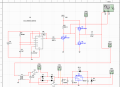
Hi, im doing this Wireless Power transfer project and I need some help. Im trying to charge a phone using inductive coupling. The problem im facing is generating the AC square wave with enough power to acutally induce something. I've come up with a MOSFET that makes a square wave with 19V peak (0V-19V) and a push pull to sink and source current. On the simulation it works fine, as the square wave actually loses it's DC component when it's induced on the second coil. Both coils are 30uH.
I tried this circuit but the push pull output on open-circuit, was really low (around 1V peak) with distortion.
My question is: can you actually use a square wave with DC component to induce voltage on another coil? Because I'm trying to avoid generating a real AC wave since I've tried that without sucess
Attachments
-
 37.6 KB Views: 22


