Inductance simualtion in LTspice

Thread Starter

captoro

Joined Jun 21, 2009
207
Hello,

I am trying to simulate an air core indutance with LTSpice. The simulation gives ideal values, and my pulsing waveform looks perfect no matter what frequency I used. I know in real life the waveform gets deformed and looks more like a sawtooth wave with a fraction of the voltage.
I found this link and many others like it:
https://www.allaboutcircuits.com/technical-articles/modeling-inductors-with-ltspice/

But nothing has worked so far, I still get ideal inductance. Has someone made a LTspice model with an good representation of a real inductor.

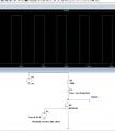
I put a screen shot, I just realized that the TanH(5*x) is what I had initially. I tried many values and also random values. So the value 222 in there is just one on the many values I tried.
I didnt realize it was that difficult to model a real life indutor.

Ken
 

Attachments

crutschow

Joined Mar 14, 2008
34,452
First you need to know the characteristics of your real life inductor before you can generate a model (inductance, resistance, stray capacitance, etc.) which you have not provided.
An air core inductor should be fairly close to the ideal.
 

ronsimpson

Joined Oct 7, 2019
3,037
What part of an ideal inductor are you trying to understand?
There should be a self resonant frequency in a real inductor. Add 5pF (more or less) across the inductor.
Also there is some wire resistance. Maybe add 1 ohm
Right click on the inductor and add 1 ohm series resistance and 5pF parallel capacitance.
 

Ian0

Joined Aug 7, 2020
9,817
At any frequency less than 4.5MHz the 5k resistance is going to dominate. At you test frequency 250Hz you will hardly notice that there is any inductance.
 

Thread Starter

captoro

Joined Jun 21, 2009
207
Did you observe that, or is it just an assumption?
I did observe this, I can take a screen shot, but its exactly as I said.
The goal is to make a simulation very close to the real life so I can compensate electronically (with a circuit of some kind) and obtain the full pulse wave in the air core inductance at higher frequencies.
 

ericgibbs

Joined Jan 29, 2010
18,849
hi @captoro
This is what LTS shows for the AC analysis, looks OK to me.
Can you confirm the quality of the signal generator you are using as an input?
Say a screenshot of the Scope showing the Input to the MOS Gate.?
Also, the SG connected directly into your Scope, showing frequency response.
EEG57_ 597.png
 

Attachments

Last edited:

ericgibbs

Joined Jan 29, 2010
18,849
hi @captoro
Thanks for the information, very puzzling.
Can you do just one more test.?
Remove the Inductor from the Drain, so only the 5K resistor is connected, run the project and check the Drain waveform.

E
 

Thread Starter

captoro

Joined Jun 21, 2009
207
hi @captoro
Thanks for the information, very puzzling.
Can you do just one more test.?
Remove the Inductor from the Drain, so only the 5K resistor is connected, run the project and check the Drain waveform.

E
HI,
I did the test without the coil and I am getting the exact same results...
So I decided to swap resistors, and same issue again. So my only other variable is the MOSFET !!.

I am going to change it and try again

ken
 

Thread Starter

captoro

Joined Jun 21, 2009
207
I think I found my issue. I have the mosfet Driver heating up too much and actually overheating and basically self destroyed itself.
That will take some time to change it, The PCB has restrictd size. This is in a TSSOP package..
Passing heat sink or Fan would be better ?
 
Top