
I have 4 lights in a crawl space that frequently get left on so a few years ago I added a switch with a neon indicator. This 120vac circuit has (2) 3-way switches, so the switch I added was a 3-way. All was well. The other day my wife mentioned that the lights were on when in fact I had just turned them off. Yes, the neon lamp was lit even with the circuit off. Pull out the switch and I read 50vac across the indicator. Ground and neutral check out ok. Once I thought through the circuit and realized that the 50vac was showing up on a wire that was floating on the other end, it occurred to me that this must be very low current induced voltage - enough to almost fully light the neon lamp.
Scratch head for a few minutes and then employ the age-old engineering troubleshooting approach by asking "what changed?". Turns out I recently swapped out the 4 bulbs for LED models. Since the neon lamp is in paralllel with the bulbs, the traditional bulbs had low enough resistance to sink the induced voltage, and evidently the LED bulbs have a higher resistance allowing the induced voltage to settle at around 50vac. To test this theory I put back one of the original bulbs and problem solved. I could just leave it like this but I really wanted to go all LED. So it seems rational that a resistor of the correct value in parallel could drop the current when off. But when the lights are on, that resistor would be across the 120vac and probably make a "sparkler".
I am wondering if a resistor in SERIES would drop the induced voltage enough to leave the indicator off when the lights are off, but still pass enough voltage when the lights are on. Since this is an integrated lamp/switch I don't know any of the characteristics of the neon bulb. Are there any general guidelines for these bulbs? If I can identify a minimum required voltage to light and a voltage at which there is NO light, possibly a resistor will reduce the voltage enough to meet both requirements?
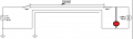
I found a generic 3-way circuit diagram and crudely sketched in the red indicator.

Scratch head for a few minutes and then employ the age-old engineering troubleshooting approach by asking "what changed?". Turns out I recently swapped out the 4 bulbs for LED models. Since the neon lamp is in paralllel with the bulbs, the traditional bulbs had low enough resistance to sink the induced voltage, and evidently the LED bulbs have a higher resistance allowing the induced voltage to settle at around 50vac. To test this theory I put back one of the original bulbs and problem solved. I could just leave it like this but I really wanted to go all LED. So it seems rational that a resistor of the correct value in parallel could drop the current when off. But when the lights are on, that resistor would be across the 120vac and probably make a "sparkler".
I am wondering if a resistor in SERIES would drop the induced voltage enough to leave the indicator off when the lights are off, but still pass enough voltage when the lights are on. Since this is an integrated lamp/switch I don't know any of the characteristics of the neon bulb. Are there any general guidelines for these bulbs? If I can identify a minimum required voltage to light and a voltage at which there is NO light, possibly a resistor will reduce the voltage enough to meet both requirements?
I found a generic 3-way circuit diagram and crudely sketched in the red indicator.
Attachments
-
 12.3 KB Views: 2


