Facebook
 Google
 GitHub
 Linkedin
Hi everyone.
I´m developing a timer based on this project: http://extremeelectronics.co.in/avr-projects/avr-project-digital-stop-watch-with-atmega8/
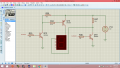
At first, I made the same schematic (as in the image) with 13mm x19mm and 5V displays and it works fine. The displays work perfectly. Then I change the displays by larger 12V display (something like 5cm x 10 cm). Now, I have a problem: the segments of the display dont turn off at all.
I supply the display with 12V throught BC558 transistor and when I want to show a number: 1, for example, the others segments of the display dont turn off, them only dim a little bit. Later I tried many ideas about the origin of the problem we saw that the problem is this (or we think so): the digital signal from the microcontroller is 0V (to turn on the segment) or 5V (to turn off the segment). The low voltage works fine to turn on the segment because the voltage throught the led is 12V (bigger than threshold voltage), but the high voltage dont woks to turn off because the voltage trought the led is 7 (12V from the transistor - 5V from the micro) and this voltage can turn on the segment (a little dim). So we try to increase the voltage from the pin of the micro using a common emitter transitor (emmiter to 10k resistor to ground, base to the micro pin and collector to 12V) and a lot of other configurations, even with an op amp in compare mode. All this in order to increase the voltage of the digital signal to 12V. But all this doesnt works.
Excuse me for the large explanation. Now, can someone help me to know how can I solve this problem.
Thanks in advance.
Bye
I´m developing a timer based on this project: http://extremeelectronics.co.in/avr-projects/avr-project-digital-stop-watch-with-atmega8/
At first, I made the same schematic (as in the image) with 13mm x19mm and 5V displays and it works fine. The displays work perfectly. Then I change the displays by larger 12V display (something like 5cm x 10 cm). Now, I have a problem: the segments of the display dont turn off at all.
I supply the display with 12V throught BC558 transistor and when I want to show a number: 1, for example, the others segments of the display dont turn off, them only dim a little bit. Later I tried many ideas about the origin of the problem we saw that the problem is this (or we think so): the digital signal from the microcontroller is 0V (to turn on the segment) or 5V (to turn off the segment). The low voltage works fine to turn on the segment because the voltage throught the led is 12V (bigger than threshold voltage), but the high voltage dont woks to turn off because the voltage trought the led is 7 (12V from the transistor - 5V from the micro) and this voltage can turn on the segment (a little dim). So we try to increase the voltage from the pin of the micro using a common emitter transitor (emmiter to 10k resistor to ground, base to the micro pin and collector to 12V) and a lot of other configurations, even with an op amp in compare mode. All this in order to increase the voltage of the digital signal to 12V. But all this doesnt works.
Excuse me for the large explanation. Now, can someone help me to know how can I solve this problem.
Thanks in advance.
Bye