incircuit programming circuit quiries.

Thread Starter

ak52

Joined Oct 15, 2014
241
Hello everyone,
I am going to use the pickit-3 for programming and debugging purposes.
I have a doubt regarding the MCLR pin connection and operation
Currently i have MCLR pin and VDD pin tied to the same supply rail directly.
Will this be a problem?
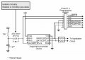
I am asking because as per the PICkit3 manual there is a 50K ohm resistor in between MCLR pin and VDD.
Also will the pickit 3 drive the MCLR pin when connected or is it the other way around?
Here are the 2 circuits :
upload_2014-11-10_12-31-42.png

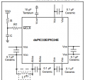
And my target circuit configuration as per datasheet
upload_2014-11-10_12-32-34.png
R = 10K,R1 = 470 ohm
Currently i am taking MCLR pin connection to PIckit3 header(pin 1) after R1 resistor.
And i am taking VDD(pin2) from "R"
 

Attachments

Last edited:

adam555

Joined Aug 17, 2013
858
The Vpp/MCRL has 2 functions: it provides 12v for programming the chip, and then as an input for the MCRL -if you configure it that way-. You should have both separate, as the Vpp is 12v and the Vdd is the supply voltage for testing the chip while connected to the PICKit with 2.5v to 5v.

The resistor you mention is a pull-up for the MCRL function; it doesn't mean that both pins can or should be connected together.
 

Thread Starter

ak52

Joined Oct 15, 2014
241
Hello adam,
Thank you for such a quick reply.
I get it that we have to separate VDD from Vpp/MCLR when ICSP is in use.and that is done through a resistor(R in above image).But two resistors are used in the recommended connections image (R and R1),R is the pull up resistor and R1 is the current limiting resistor.I plan to use R1 of about 330 ohm.

Should i connect Vpp of the pickit before or after the current limiting resistor?
 

adam555

Joined Aug 17, 2013
858
I'm attaching an example of how it should be connected. But mind that the limiting resistor is only needed if you intend to use a push button for the MCLR or intend to use that pin as an input. If you are not using the push button, only the pull-up resistor is needed. And if you have the MCLR disabled in your configuration, then only Vpp needs to be connected alone without any of those 2 resistor.
 

Attachments

Thread Starter

ak52

Joined Oct 15, 2014
241
I'm attaching an example of how it should be connected. But mind that the limiting resistor is only needed if you intend to use a push button for the MCLR or intend to use that pin as an input. If you are not using the push button, only the pull-up resistor is needed. And if you have the MCLR disabled in your configuration, then only Vpp needs to be connected alone without any of those 2 resistor.
thank you mate,yes i am using a push button reset switch across the resistor also but when programming i will remove the capacitor (via a jumper),as mentioned in the datasheet.

Also can you suggest me a good communication cable which i can use to connect the pickit to the target board.
Sad thing is there isn't any locking mechanism adopted in the pickit so if the 6 pin header is interchanged by accident it can harm the target or the programmer.
I was thinking one end 6 pin male header the other end a D-SUB 9 connector.
Any other suggestions are welcome..
 

BobTPH

Joined Jun 5, 2013
11,515
Connect the MCLR pin directly to the ICSP header, pin 1. You can then leave the rest of your circuit as is when programming. The purpose of R1 is to isolate the capacitor from the programmer so that it does not prevent the programmer from switching MCLR quickly.

Bob
 
Top