Improvised Ballast for Coronavirus UV Lamp

Thread Starter

Kdt

Joined Apr 6, 2020
10
Hi,

I met a doctor on Helpful Engineering who has no ballast for his UV sterilizing lamp, this one:
https://www.lighting.philips.com/ma...r-and-air/tuv-tl-mini/928001104013_EU/product
It is an 8W T5 tube. He is in India and has no way to get a proper ballast right now, so we're trying to improvise, but I have no practical experience in lighting and hoping for help to get the lamp working.

He has three ballasts:
1. 36W electronic ballast: https://www.bestofelectricals.com/philips-36-w-sumo-ultra-electronic-ballast
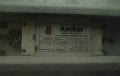
2. An old Anchor 18W ballast, can't find it online (see image). He says it is from a T8 lamp.
3. Old Chinese 21W electronic ballast (see image)
He also has assorted spare parts and tools. Since he only has one tube, we need to be careful not to ruin it.

I am thinking that the 36W ballast is a no go because that's just too much power. I know that you can try using a wrong ballast and it could work for some period of time, but I don't know how sensitive it is (10W ballast maybe ok for 8W tube, but 18W is pretty high).

So I want to ask for him:
1. How much range is there in the ballast you use for a given tube? Is one of the existing ballasts ok?
2. He could use the 18W or 21W ballast and add some series resistance to dissipate the excess power. Since the tube impedance changes during operation, is it possible to pick a constant resistance that would dissipate appropriate power across the range of lamp operation?
3. There is some voltage spike required to start the lamp, so I presume that a series resistance would divide the voltage too small to start the lamp while limiting current properly(?).
4. Could he add a resistance parallel to the tube divide current and dissipate power? This wouldn't change with the tube voltage, but, again, not sure how to calculate properly due to the tube's changing electrical parameters.

I am also thinking that it is marginally possible to build an RLC ballast, but not sure how to do it confidently.

Thank you so much for your advice!
 

Attachments

Thread Starter

Kdt

Joined Apr 6, 2020
10
Awesome, thanks for the fast reply! Can I ask, how did you find out? I couldn't find anything on that one. Also, wouldn't that one be designed for a tube that can dissipate a lot more power? He only has an 8W lamp.
 

jpanhalt

Joined Jan 18, 2008
11,087
That bulb does not look like a UVC low-pressure mercury lamp. Does the person you are working with know what type of bulb that is? Does he have a proper bulb?

Something that gives a false sense of security can be far worse than not having it at all. Think of a parachute packed with old rags instead of a parachute.
 
Last edited:

LesJones

Joined Jan 8, 2017
4,190
If you click on the first link in post #1 then click on leaflet it takes you to a data sheet that is quite detailed. It gives the tube voltage as 56 volts and the tube current as 0.15 amps. I think the important thing is to control through the tube. I think if you use the 18 watt ballast you you should check the current to make sure the lamp is not being overdriven shortening it's life or underdriven which would reduce it' UV output. (It may also flicker on and off if the current was too low to keep the cathodes hot enough.) I have a UV light box that I made many years ago for erasing EPROMs. It uses a similar tube and I just use an inductive ballast from a normal 8 watt fluorescent light. The normal flourescent and the UV version were the same physical dimensions.

Les.
 

Thread Starter

Kdt

Joined Apr 6, 2020
10
Thanks to both for your inputs.

jpanhalt: He said he bought it online, so he should have the TUV 8W FAM tube. The datasheet says it's mercury. But he only has the one of them.

LesJones: Yeah, I've seen the datasheet. I was thinking that the 18W ballast would supply too much power and ruin the tube. If it does even start the tube, then sure, he could measure it and check, but I'm worried that it could burn out first. 18W is over twice the tube's power rating. With your light box, it sounds like your ballast and tube were properly matched.

What do you guys think of using the 18W ballast and adding a resistance parallel to the tube to dissipate 10W? At 56V, 18W uses 322mA. The tube draws 150mA, so we would need the resistance to draw 172mA. At 56V, that would be 326 ohms. I think this would protect the tube from excess current while preserving the voltage from the starter.
 

LesJones

Joined Jan 8, 2017
4,190
I don't think that you can assume that the voltage across an 18 watt tube is the same as an 8 watt tube. I suspect that an 18 watt tube will be longer so it will have a larger voltage across the ends. (So the current would be less than the simple ratio 18/8) Also during the starting phase there is just the ballast and the two cathode heaters connected across the mains until the starter switch opens to create the high voltage pulse that starts the ionization of the gas in the tube. (The voltage across the heaters is only a few volts) This could possibly burn out the heaters. Putting a resistor in parallel with the tube would do verey little to reduce the current though the heaters. Also it could shunt the high voltage start pulse so the tube did not start. Is it not possible for him to buy a standard 8 watt fluorescent light fitting from a DIY store or an electrical wholesaler and just swap the tubes.

Les.
 

Thread Starter

Kdt

Joined Apr 6, 2020
10
I think you're right about tube voltage. But we know that the ballast supplies 370mA (just realized this) and that the tube voltage is 56V at 150mA. So by controlling the current through the tube, we would also be controlling the voltage, no matter what voltage an 18W tube would be.

I didn't consider burning out the heaters. Are you saying that by maintaining the 56V across the tube, as opposed to the higher voltage that a longer tube would be, the voltage across the heaters would rise to compensate and ruin them? But I don't think a parallel resistor could shunt the voltage pulse because they're parallel, so they experience the same voltage.

Unfortunately, India is basically locked down at the moment. So it's like he's on an island with what he has.
 

jpanhalt

Joined Jan 18, 2008
11,087
jpanhalt: He said he bought it online, so he should have the TUV 8W FAM tube. The datasheet says it's mercury. But he only has the one of them.
Mercury low-pressure lamps that are used to kill germs are usually clear. This is a typical output spectrum from such lamps:
1586279089332.png
Over 90% of the output energy is at 2537 angstroms (254 nm). Germicidal activity occurs over a broad band with a peak at about 265 nm, so they are close to ideal for that Another factor is the type of envelop used. For 254 nm, quartz is very efficient. Soft glass may be used, but typically only passes about 30% of the light produced by the mercury vapor.

The envelop tubes of low-pressure mercury lamps are often coated with phosphors that absorb the 254 nm light and emit at a longer visible wavelengths. Those phospohros are usually white when the bulb is off, but than can be almost any color. Typical fluorescent lamps for lighting are not germicidal, but they are mercury based.

There are simple ways to test for appropriate UVC, Zn2SiO4 (zinc silicate, https://en.wikipedia.org/wiki/Willemite ) fluoresces green under short wavelength UV. You can buy that by itself, but it is probably easier and cheaper to stop by any chemistry lab and ask to use a small piece of one of its TLC plates (https://labchem-wako.fujifilm.com/us/category/00973.html ). It can be a previously used plate too.

Given the suspicion that such lamps are rarely coated with phosphors (I have never seen a 254 nm light that was coated), I would not put much weight on an unbranded lamp that someone said had mercury in it. It probably does, but it is not likely germicidal.

Edit: Just saw you more recent post. If it is not germicidal, it doesn't make sense to use and may give a false sense of security, which can be more dangerous.
 

Thread Starter

Kdt

Joined Apr 6, 2020
10
Now I see what you mean. I didn't realize that they are generally clear, so definitely agreed about false sense of security, and thanks for all the details. Maybe he can test it.
 

LesJones

Joined Jan 8, 2017
4,190
I was wrong in guessing that the voltage across the 18 watt tube would be higher than the 8 watt tube. As the tube is 18 watts and the current is 0.37 amps the voltage across the tube will be 18/0.37 = 48.6 volts. If he could find another 18 watt ballast then using two in series would be about right.

Les.
 

Dodgydave

Joined Jun 22, 2012
11,303
The Voltages from the ballasts are all the same approx 250 to 300V AC, the difference in higher ballasts is the current output available to run bigger tubes, or twin tubes.
You can get a ballast from any CFL bulb, just break into the fitting and remove the pcb, that's what i did for my fish pond UV light..!!


Last edited:

Thread Starter

Kdt

Joined Apr 6, 2020
10
He did verify that the tube is the correct type. He had some images of it yesterday that I didn't find. The video from Dodgydave would be a good quick fix, but how does it work if it is 250-300V, and standard ones are like 40W? I guess it worked for you, but I would think you still need to limit the current, and then add series resistors to divide the voltage down to 56V.
 

Janis59

Joined Aug 21, 2017
1,849
1) There are the giant difference between bactericide lamps and viracide lamps. First are working within glass pipe having sth shorter than 320 nm. Second may work only alone the quartz tubulus, thus the 254 nm Hg lamps are most widespread. Any Solarium lamps 320-420 nm are completely useless. Rather good are street lamps of water-melon sized bulb, that must be crushed accurately let the inner quartz bulb of finger size is alive. All resistors over it must be salvaged. Dont mistake with Natrium lamps those of cabbage size, that are aimless. Must be Hg inside.
2)Thus, You have at hands the quartz Hg lamp - may happen it is low pressure or high pressure but both must be used in identical circuit like long tube daylight lamps, except the starter and filament. So, lamps are switched via coil in series to the standard network 220V 50 Hz. If one have 60 Hz, its OK, if the Voltage is 240, 230 its OK, but 110V it never will ignite, however the normal voltage of both is ca 30-40 V at smaller current than nominal and up to 100V at nominal. As the nominal current is most cases bit too much for human, the good news is that burning at even so low that 10% of nominal currents yet is stable and useful. So, only must never be done is to over-exceed the nominal. Thus any standard choke is good. Most available those are from long luminiscent lamps, from 0,65A, 0,45A, 0,36A, 0,23A etc. But there is one problem, normal long lamp have 140V on it, thus the coil sees only 220-140=90V, but with UVC lamp it have 220-30=190V. Thus, even at hardly less than nominal current thiose coils are overheating in first five to ten minutes. If the work is intended be short-time, then may screw some 4 mm thick aluminium plate about 5x10 inch below the coils - then some half of hour or hour it may persist. If not, there are no other choice as to connect the two coils in series and two such series in parallel. Then 4 coil matrix works very well thermally, without of any radiator.
3) So, You need a lamp, You need a numerous coils of longlamps, and need a fixtures for lamps - never dont forget that normal lamp temperature must stay between 240 and 280 C thus the safety duistance of at lest 4 inches is mandatory. I am using 0,5 mm walled metal piece of 1 cm wide and 15 cm long. Lover end is fixed to wooden planck, say 1x5x12 inch, on what the lamp and drossels are fixed. At March I produced such many dozens, all them works well up today.
4) Technically, there are two effects from lamps, straight UVC demanding 4 W/m2 for killing 3,5 orders of magnitude downward the viral concentration in ONE MINUTE. Proportionally 10x smaller brightness will demand 10x longer cure time. Second effect is by-generation of ozone, where 4 mg/m3 kills this virus in 1 minute, yet the 0,12 mg/m3 is clear too much for human even in one short-term exposition, and nose sensitivity threshold for ozone is somewhere between 0.04 and 0.10 mg/m3, thus if the smell becomes strong, means it is too much. Warning, 1000W of UVC kills the eysight for week in about 1 second.
5) About ignition - just plug-deplug-plug-deplug whilst it is started. Coil is giving rather good splash at disconnecting. If no, may roll some turns of wire on glass near the lamps end and via the 2W 13 kOhm set to the contrary end of lamp. Then ignition happens much easier
 
Last edited:

jpanhalt

Joined Jan 18, 2008
11,087
The tube in the first link, as posted by Les, looks right. I refused t accept the cookies, so didn't see it clearly. My comments were with respect to the tube shown with the ballast, which has a phosphor coating. I agree that the clear tube shown by Les is the correct type.
 

Janis59

Joined Aug 21, 2017
1,849
Some illustrations of right type of lamps
Low pressure HG lamp 400W https://images.ru.prom.st/507285973_w640_h640_lampa-ultrafioletovaya-drt-400.jpg
High pressure Hg lamp 200W http://medikosnab.ru/image/cache/catalog/new/1229/3557-800x800.jpg
Wrong type of lamp, Natrium https://sc01.alicdn.com/kf/H001ca60.../70w-150w-250w-sodium-steam-high-pressure.jpg
Large street lamp 400/800/1000W https://im0-tub-ru.yandex.net/i?id=6ab5264062543fb6fa680a503b5a2d2c&n=13
Hre what it contains inside, so outside must be crushed but inside saved. https://www.syl.ru/misc/i/ai/183109/749684.jpg
 

Thread Starter

Kdt

Joined Apr 6, 2020
10
Thanks for the advice on the lamps! He verified that he does indeed have the right kind, so now just trying to figure out the circuitry.
 

LesJones

Joined Jan 8, 2017
4,190
I was not impressed by the Youtube video. There was no mention of selecting a CFL lamp that had a similar rating to the tube that it was being used with. For a none technical person there was no information on how to identify the connection points. (For a technical person they would not need the video anyway.) At the end of the video the tube seemed to be flickering so it was not being driven correctly. I have in the past thought of doing that but have never tried it.

Les.
 
Top